5.2 Normalized Power Waves
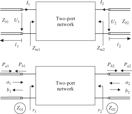
Let us consider the two-port network in Figure 5.2. The network is connected to two transmission lines with characteristic impedances Z01 and Z02.
Figure 5.2 Definition of incident and outgoing power waves ai and bi at a two-port network attached to transmission lines with characteristic impedances Z01 and Z02.
In Section 3.1 we discussed transmission lines and propagating voltage and current waves. We introduced a forward propagating voltage wave Uf and a reflected (backward travelling) voltage wave Ur. Based on these voltage waves we now derive normalized power waves by dividing the voltage waves by the square-root of the characteristic line impedances [1].
We define a forward propagating normalized power wave as
where i is the port index (i ∈ [2, 3]). Furthermore, we define a backward propagating normalized power wave as
For loss-less transmission lines the characteristic impedances are real-valued.1 The impedances are also referred to as port reference impedances. Most often we use port reference impedances that equal the common2 system impedance of Z0 = 50 Ω. Throughout this book we assume port reference impedances of 50 Ω, if not otherwise ...
Get RF and Microwave Engineering: Fundamentals of Wireless Communications now with the O’Reilly learning platform.
O’Reilly members experience books, live events, courses curated by job role, and more from O’Reilly and nearly 200 top publishers.

