3.1 Transmission Line Theory
3.1.1 Equivalent Circuit of a Line Segment
Let us consider the two-conductor transmission line in Figure 3.1a.
Figure 3.1 (a) Geometry of a two-wire line and (b) distribution of electric and magnetic field strength in a cross-section.
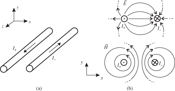
The two conductors are surrounded by a homogeneous material (for instance air). The currents I+ and I- are equal to each other but flow in opposite directions. The transmission line extends in ±z-direction. The cross-section of the line is independent of the local coordinate z. The currents on the conductors produce a circulating magnetic field around the wires (see Figure 3.1b). Furthermore, there is a voltage between the conductors. Hence, we see an electric field starting at one conductor and ending at the other.
If we considered transient signals we would see a wave travelling down the line due to the finite propagation speed of the electromagnetic phenomena. The electric and magnetic fields on the transmission line are perpendicular to each other and perpendicular to the direction of the wave. Therefore, our two-conductor line carries a TEM wave, where TEM stands for transversal electromagnetic. A TEM wave represents the fundamental wave mode that can propagate on a transmission line. The TEM mode1 is able to propagate in the entire frequency spectrum with the same speed. The speed depends solely on the material ...
Get RF and Microwave Engineering: Fundamentals of Wireless Communications now with the O’Reilly learning platform.
O’Reilly members experience books, live events, courses curated by job role, and more from O’Reilly and nearly 200 top publishers.

