In addition to the switch, the circuit includes a resistor in series with the switch to protect the GPIO pin, as shown in the following diagram:
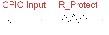
A GPIO protective current-limiting resistor
The purpose of the protection resistor is to protect the GPIO pin if it is accidentally set as an output rather than an input. Imagine, for instance, that we have our switch connected between the GPIO and ground. Now the GPIO pin is set as an output and switched on (driving it to 3V3) as soon as we press the switch, without a resistor present, the GPIO pin will be directly connected to 0V. The GPIO will still try to drive it to 3V3; ...

