Connect the switches to the GPIO using a method similar to the one we used in Chapter 9, Using Python to Drive Hardware, for the D-Pad controller. A circuit diagram of the switches is as follows:
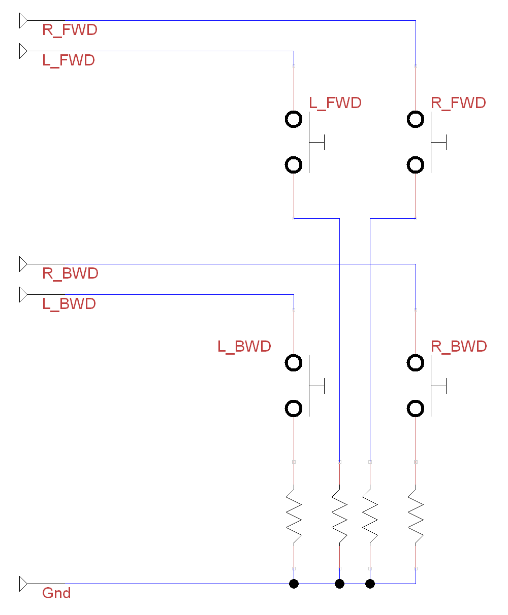
The switches should include current limiting resistors (1K ohm is ideal)
How you connect to the Raspberry Pi's GPIO will depend on how your motor/servo drive is wired up. For example, a Rover-Pi robot with an H-bridge motor controller can be wired up as follows:
|
Control side of the module – connecting to the Raspberry Pi GPIO header |
|||||||
|
ENA |
IN1 |
IN2 |
IN3 |
IN4 |
ENB |
GND |
5V |
|
None |
Pin 15 |
Pin 16 |
Pin 18 |
Pin 22 | |||

