The H-bridge motor controller recreates the previous switching circuit with additional circuitry to ensure that the electronic switches cannot create a short circuit (by not allowing SW1 and SW3 or SW2 and SW4 to be enabled at the same time).
The H-bridge motor controller's switching circuit is shown in the following diagram:
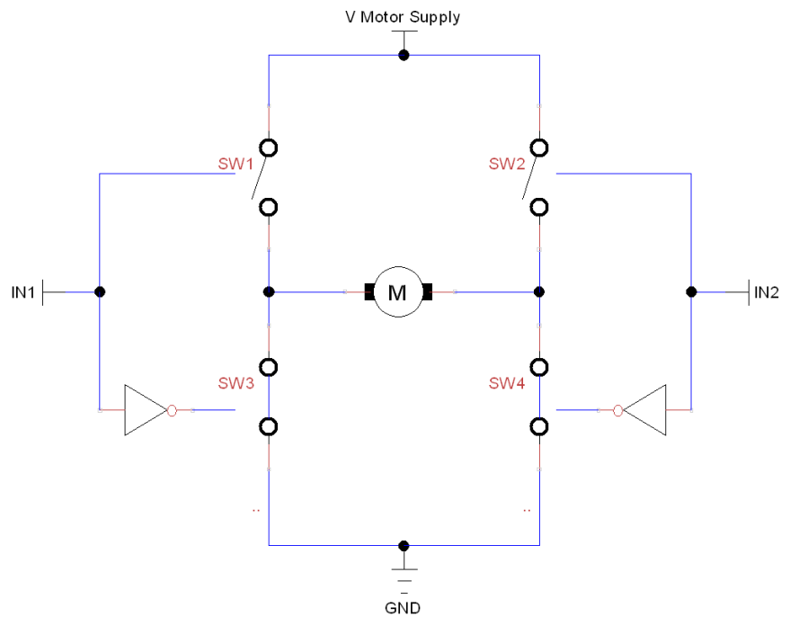
An approximation of the H-bridge switching circuit (in motor off state)
The input (IN1 and IN2) will produce the following action on the motors:
|
IN1 IN2 |
0 |
1 |
|
0 |
Motor off |
Motor backwards |
|
1 |
Motor forwards |
Motor off |
As we did in the previous recipe, we can move forward by driving ...

