A circuit diagram of the PCF8591 module without the sensors attached is shown in the following diagram:
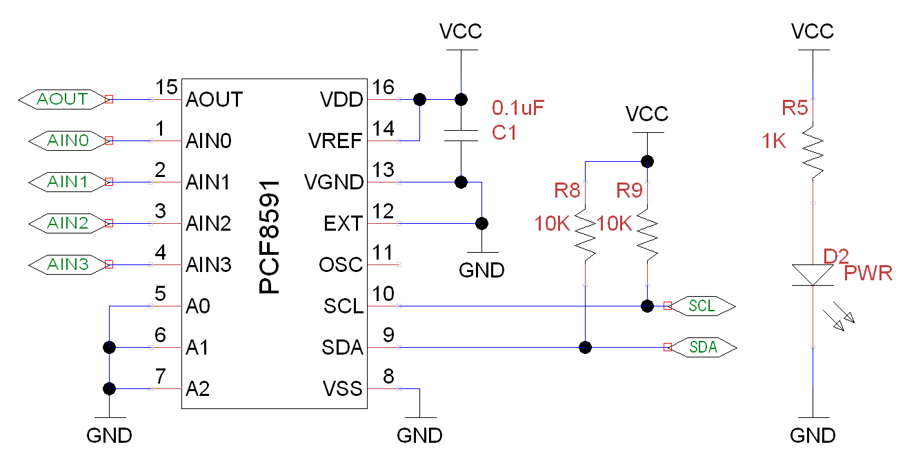
Circuit diagram of the PCF8591 module without sensor attachment
As you can see, excluding the sensors, there are only five additional components. We have a power-filtering capacitor (C1) and a power-indicating LED (D2) with a current-limiting resistor (R5), all of which are optional.
Note that the module includes two 10K pull-up resistors (R8 and R9) for SCL and SDA signals. However, since the GPIO I2C connections on the Raspberry Pi also include pull-up resistors, these are not needed ...

