10.3. SYSTEM BRINGUP EXAMPLE
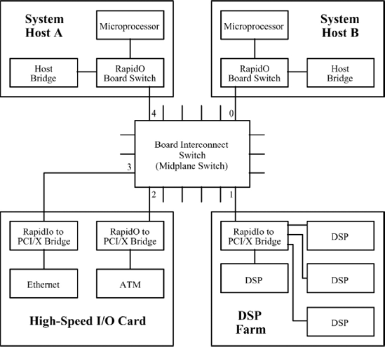
This example shows the process employed by a system that offers two host processors, a single switch and two resource board subsystems. The hosts (A and B) are redundant with each other. Host B is assigned a higher priority than Host A. To better demonstrate the enumeration interaction between the host devices, Host A begins the enumeration process first. Figure 10.1 provides a representation of the system connectivity and topology.
The following additional assumptions are made about the example system: system Host A is preloaded with device ID 0×00 and system Host B is preloaded with device ID 0×01. System Bringup advances through a series of time steps. The time steps are not meant to be of equal length, but they would occur in the specified order. The following time steps would occur as the enumeration process proceeded:
Figure 10.1. Example system
T+0: Host A begins RapidIO enumeration.
T+1: Host B begins RapidIO enumeration and Host A continues RapidIO enumeration.
T+2: Host B discovers another host in the system (Host A) and waits.
T+3: Host A discovers a higher-priority host in the system (Host B) and retreats.
T+4: Host B assumes sole enumeration of the system.
T+5: Host B enumerates the PE on switch port 1.
T+6: Host B enumerates the PEs on switch ports 2, 3 and 4.
T+7: System enumeration is complete.
The following describes the actions taken during ...
Get RapidIO: The Next Generation Communication Fabric For Embedded Application now with the O’Reilly learning platform.
O’Reilly members experience books, live events, courses curated by job role, and more from O’Reilly and nearly 200 top publishers.

