14.2. IMPLEMENTING A RAPIDIO END POINT
14.2.1. End Point Overview
The RapidIO specification dictates that each interface on a RapidIO device must process both inbound and outbound transactions simultaneously. The inbound and outbound modules of the RapidIO interface can be designed separately or as one block. In either case, the inbound and outbound modules in the physical and transport layers must communicate.
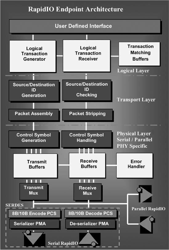
For our sample end point, shown in Figure 14.2, the inbound and outbound are separate blocks, transferring packets in through the inbound module and routing them out to a user-defined interface (UDI) for processing within the end point.
The following list gives some sample features that can be implemented in a RapidIO end point:
Full duplex operation
Destination ID (DestID) mapping tables
Large (16-bit) and small (8-bit) system device ID
Multicast-event control symbol
Receiver link level flow control/transmitter link level flow control
Error management capability
Port-write operation for error reporting
Data plane extensions
Sample features of a parallel end point:
Full-duplex, double-data rate (DDR) RapidIO
Operating frequencies of each interface can be configured separately (different clock rates)
LVDS signaling
Figure 14.2. RapidIO end point block diagram
Sample features of a serial end point:
Ports that can operate in 1x mode or 4x mode (different clock rates)
SERDES with 8b/10b ...
Get RapidIO: The Next Generation Communication Fabric For Embedded Application now with the O’Reilly learning platform.
O’Reilly members experience books, live events, courses curated by job role, and more from O’Reilly and nearly 200 top publishers.

