16.2. CHANNEL CHARACTERISTICS
While these RapidIO switched electrical signaling features are helpful, the ultimate suitability of a signaling technology to a particular mechanical environment needs to be carefully evaluated. At these high signaling rates, the transmission line effects as well as the frequency-dependent loss of the channel must be considered. A combination of measurement, modeling and simulation should be used to validate the signal integrity of a given mechanical application.
Figure 16.1. Backplane example
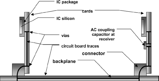
The important channel elements of a backplane application are illustrated in Figure 16.1. The effects of these elements on loss, reflection, crosstalk and skew should be evaluated. The printed circuit traces of the cards and backplane are the largest contributor to signal loss. Impedance discontinuities between IC package, vias, traces, and connectors and even within traces, connectors and IC packages can all generate signal reflections. Connectors, traces, vias and IC packages can all introduce crosstalk in the multiple signals of a system, thus further reducing a signal's integrity. Skew, both within a differential signal pair and between pairs, is another consideration. Finally, at these high frequencies even the stub-length effects of a via can be an issue.
A model of a complete channel can be assembled from models of the various elements present in the ...
Get RapidIO: The Next Generation Communication Fabric For Embedded Application now with the O’Reilly learning platform.
O’Reilly members experience books, live events, courses curated by job role, and more from O’Reilly and nearly 200 top publishers.

