APPENDIX CDouble-Tuned Matching Circuit Example
Assume that an impedance transformation is required between a 50-Ω source and a 15-Ω load. The matching is to be done using the double-tuned matching circuit described in Chapter 3 using the program DBLTUNE. The center frequency is at 4 MHz, the bandwidth is 100 kHz, and the pass-band ripple is 0.5 dB. The capacitances and transformer parameters are to be determined. In the following computer output, the bold characters are the responses the program expects from the user. Furthermore, in this example, the verbose mode is chosen by choosing to display the intermediate results. An analysis of this circuit using SPICE is shown in Fig. C.1.
FIGURE C.1 Double-tuned matching circuit example.
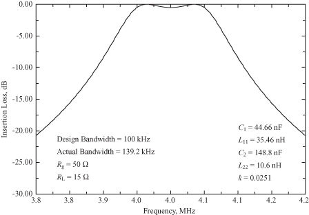
Display intermediate results? < Y/N > YCenter Freq, Bandwidth (Hz) = ? 4.E6, 100.E3Fm1 = .396480E+07 Fm2 = .403551E+07GTMIN = .99992E+00Passband ripple in dB = ? 0.5Resistance Ratio r = .19841E+01Q2_m1 = .97432E+00 Q2_m2 = .10097E+01Generator and Load resistances values = 50., 15.L2’ = .56259E+02 μH C2’ = .28140E+02pFRL’ = .79332E+05 Bm1 = .19480E-01 Bm2 = -.20193E-01Given terminal resistances: RG = .500E+02 RL = .150E+02Input Circuit: C1 = .446554E+05pF L11 = .354637E-01μHOutput Circuit: C2 = .148828E+06pF L22 = .106441E-01μH Transformer coupling coefficient k = .250991E-01

