18.6 THE PROCEDURE TO DESIGN COUNTERS
The major in the design of counters is briefly described here:
- The statement of the problem or the state diagram will be given.
- Identify the number of flip-flops required.
- Choose the type of flip-flop needed.
- Assign variable names to the flip-flops.
- Draw the state table.
- Develop the excitation table.
- Use a K-map to derive the logic equations.
- Implement a counter to produce the specified sequence of states.
This design procedure can be further understood with the help of the following example.
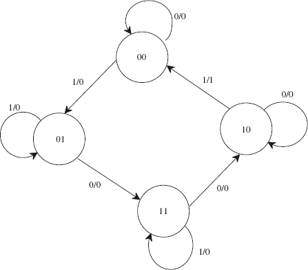
FIGURE 18.24 A state diagram
EXAMPLE
Example 18.4: Design a 3-bit binary counter whose state diagram is shown in ...
Get Pulse and Digital Circuits now with the O’Reilly learning platform.
O’Reilly members experience books, live events, courses curated by job role, and more from O’Reilly and nearly 200 top publishers.

