The word Arduino refers to three separate tools, which, bundled together, create the toolkit that we refer to as Arduino. First, there is the Arduino controller, which exists in several forms, from large to small to a freely available schematic that anyone with the requisite knowledge can assemble. Second, there is the language and compiler, which creates code for this microcontroller, and which, much like the Processing language, simplifies many of the tasks that challenge designers and developers alike when working with hardware and physical interaction. Finally, there is the Arduino programming environment, which, again like the Processing IDE, is a simple open source IDE built in Java. Therefore, because the word Arduino can have several meanings, I’ll be quite specific when referring to a particular aspect of the environment, such as the Arduino language. When I simply refer to Arduino, I’m referring to the environment as a whole.
So, with that established, what is Arduino? It’s a goal, and that goal is to simplify the creation of interactive applications or objects by simplifying the programming language used to create instructions and by providing a powerful yet basic controller that can easily be used for many common programming tasks while still being robust enough to support more complex projects. The Arduino controller is one of the most remarkable and popular open source projects because it enables so much. Programming microcontrollers can be, to the untrained, daunting and frustrating. Yet, being able to create working computers the size of a matchbox that can easily interact with hardware opens up an entirely new world of possibilities to interactive designers and artists.
Tinkering is what happens when you try something you don’t quite know how to do, guided by whim, imagination, and curiosity. When you tinker, there are no instructions, but there are also no failures, no right or wrong way of doing things. It’s about figuring out how things work and reworking them.
—Massimo Banzi, one of the originators of the Arduino project
What sorts of things do people make with Arduino? They create physical controls that people can interact with, including buttons, dials, levers, and knobs. They create interactive environments that use weight sensors, ultrasonic and infrared sensors, and temperature sensors. They create ways to control their appliances, control the lights in their houses, and control video cameras or still cameras, what’s generally called home automation or a smart house. They create small robotics or mechanical toys. They create small autonomous programs that communicate with one another and send signals, thereby creating miniature or not-so-miniature networks. The potential of the controller, what it can do, and what it can enable you to do, is enormous. So, with little further ado, let’s get started.
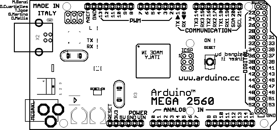
First, and perhaps most important, you’ll need an Arduino controller. When you look at the Arduino home page you’ll notice that there are around a dozen different Arduino controllers with several dozen more “Arduino-compatible” boards that can be used with the Arduino IDE and language. I recommend that beginners use the Arduino Uno. The Uno doesn’t require anything more than a USB cable to get started, which means you can begin exploring the Arduino environment just moments after you open the box. This isn’t to say that you have to use the Uno. The Arduino Mega, which provides a great deal more computational power and pins for input and output, is also an excellent choice. There is also the Arduino Nano, Pro, and the Pro Mini, all of which are smaller and easier to operate; you might explore these later after you’ve grown more comfortable with the Arduino. All of these are available from a great number of online electronics supply stores; a quick online search will be able to guide you to a few places.
You’ll also need a USB cable with one end that is USB A and the other USB B, as shown in Figure 4-1.
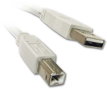
You’ll use the USB cable to connect the Arduino controller to your computer, since the Arduino controller connects only with the USB B (the square shape), and most computers use only the USB A (the rectangular shape). If you don’t have an Uno or similar board that has a built-in LED, it’s also recommended that you purchase an LED light from an electronics store for testing purposes. Using a blinking light is a great way of verifying that the board is working and is a great tool for debugging code.
The next part of the Arduino controller that you’ll need is the IDE, which you can download from the Arduino website at http://www.arduino.cc/en/main/software. Select your operating system and download the zipped files. Once you’ve downloaded the files, unzip them. On a Mac, you should see something like Figure 4-2.
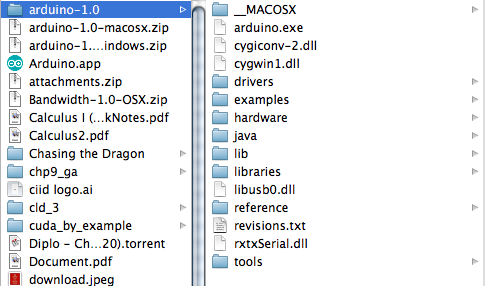
The drivers are what allow your computer to communicate with the Arduino board. Without these drivers installed, you won’t be able to communicate with the Arduino, so it’s important that they are installed before you try to upload any code. The file structure on a Windows or Linux computer will be the same, but the process for installing will be slightly different.
To install Arduino on OS X you simply drag the Arduino.app to your Applications folder and you’re done.
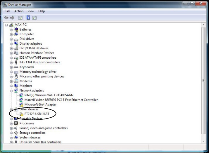
The easiest way to install the Windows drivers for the Arduino controller is simply to plug the controller in to your computer and wait for the Found New Hardware Wizard to appear. You may need to open the Device Manager, as shown in Figure 4-3.
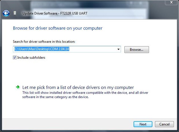
Continue to the “Please choose your search and installation options” window, and add the location of the drivers folder to the locations that Windows will search for the driver by adding it to the “Search for driver software in this location” field, as shown in Figure 4-4.
Click Next until you get to the final screen, and then click Finish. The drivers are now installed, and you’re ready to go.
I hate to perpetuate stereotypes about Linux users, but I’m going to assume that if you’re running Linux, you’re clever enough to troubleshoot a lot of the difficulties and peculiarities of your particular distribution. With that in mind, here’s a slightly more high-level overview of what’s involved in getting Arduino running on a Linux machine, because it’s a slightly more involved process. You will need to install the following programs:
The Java Runtime Engine (called the JRE)
avr-gcc (aka “gcc-avr”)
avr-libc
How you install these programs is going to depend on which
distribution you are using. You will also need a compatible kernel. If
you have brltty installed (the
default on recent versions of Ubuntu), you’ll need to remove it. Once
you’ve done this, download the latest Arduino Linux distribution,
extract these files to a directory, and run the arduino script. If you encounter
problems, consult the Linux install instructions at http://www.arduino.cc/playground/learning/linux, where
there are links to more detailed instructions for several of the most
popular Linux distributions.
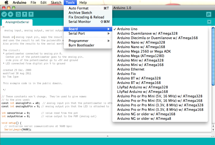
Once you’ve installed the drivers, you can run the IDE. On all systems, the Arduino IDE is an executable in the folder where the download was unzipped. You shouldn’t move the actual executable because it requires the hardware folder in order to operate correctly. Once you start up the IDE, you’ll need to configure it correctly. This means telling the IDE which board you’re using and which serial port is connected to the Arduino controller. To select the board, go to Tools→Board, and select the board type, as shown in Figure 4-5.
Next, you’ll need to select the port on which the board will operate. On OS X, this will be the option with the letters tty in it, as shown in Figure 4-6.
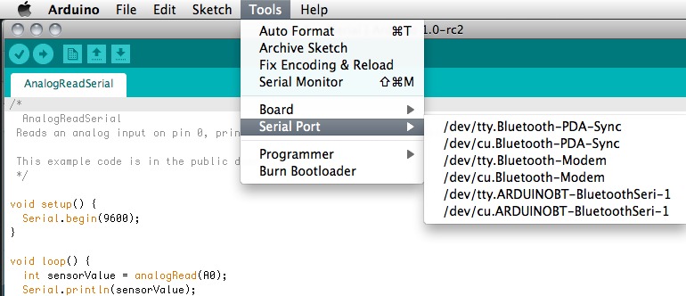
On a Windows computer, the ports will have the word COM in the title. You may need to do a little testing to determine which port is the correct one on your computer. Once you get the correct port, you’re ready to go. If you’d like to run a simple script to check whether your board is working correctly, look ahead to the section titled Touring the Arduino IDE.
Now that you know how to install the Arduino IDE and drivers, you can move on to looking at the boards themselves. Since the Uno is the easiest and most straightforward of the boards, we’ll contrast that one with some of the other Arduino controllers so you understand not only what the Uno is, but what makes it unique.
So, what is this controller? Really, it’s just the same thing as your average computer, minus the hard drive and a few other things you might be used to having. The core elements are there, however. Input/Output (I/O) is done through pins and the USB port, the processor is there, and there is a small amount of random access memory (RAM) that acts much the same as RAM in a larger computer. Of course, all of these things are on a far smaller scale than a laptop or desktop computer, which means that the engineering is quite different in some respects, and there are many different issues that you need to consider with a microcontroller that you would not need to consider with a normal computer, particularly when working with powering other devices and powering the controller itself. That said, the general principles still apply, which makes working with microcontrollers a good way to learn more about the inner workings of computers and of computing.
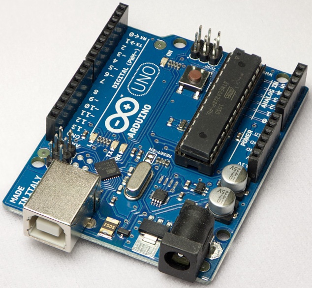
We’ll be looking at three controllers. The Uno controller, shown in Figure 4-7, is a slightly larger controller that is a little easier to work with for beginners, since components can be attached directly to the controller.
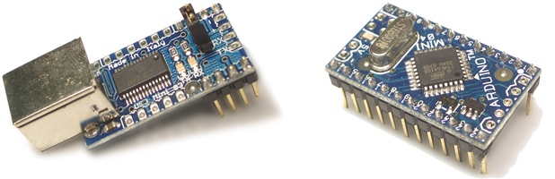
The other Arduino controller that we’ll examine is the Mini. This controller is much smaller, and that changes the types of projects that it can be used with. The Mini requires a separate USB adapter (see Figure 4-8) that allows you communicate with the controller over USB for uploading code and receiving messages over the Serial port. The Mini also requires that you purchase a prototyping board in order to wire any components to it or to power it separately from a computer using a battery. This isn’t a great impediment, and you should purchase a prototyping board anyway for doing any kind of serious work with the Arduino controller.
The Uno comes with small LED lights that you’ll find next to the USB port on the Uno. When you connect the controller to power, if there is a program currently loaded into the memory of the controller, a light should begin blinking. The Mini does not have such an easy way to tell that it’s plugged in and powering up correctly, but making a small program that can turn on an LED that is connected to one of the Mini’s pins is easy enough to do. We’ll cover doing that a little bit later in the section Hello World.
Uno means 1 in Italian and was created to mark the release of Arduino 1.0. The Uno and version 1.0 will be the reference versions of Arduino, moving forward, so learning about the Uno is a great way to learn the core fundamentals of the Arduino environment. It is designed to be easy to understand and to work for those without experience in electronics. It has 20 pins (6 analog and 14 digital), 6 pulse-width modulation-enabled pins, a TX and RX pin pairing, and an I2C port. Newer boards (after revision 3) have four additional convenience headers that mirror other pins on the board. None of that makes sense? Then read on.
A pin provides an input or output through which the controller can communicate with components. Smallish copper wires can be inserted into the pins connectors, and you’re off to the races. When you look at the Uno, you’ll see a row of small black holes along either side of the controller that a wire can be inserted into.
Digital pins have two values that can be read or written to them: high and low. High means that 5 volts (V) is being sent to the pin either from the controller or from a component. Low means that the pin is at 0 V. Now, start to imagine the sorts of information that this can encompass: on/off, there/not there, ready/not ready. Any kind of binary information can be read or written to a digital pin.
Analog pins are slightly different; they can have a wide range of information read or written to them. How wide a range? Well, from 0 to 255 can be written, which represents 256 steps of voltage information, once again starting with 0 V and going up to 5V. Analog values from 0 to 1,023 can be read (representing voltages from 0 to 5 V in 0.005 V increments). These pins are what we use to read and write information that has a range of values, such as the position of a dial, the distance of an object from an infrared sensor, or the brightness of an LED light. In addition to the digital and analog pins, there are connectors relating to the powering of components.
Figure 4-9 shows the Uno. Note that the digital pins are at the top of the picture. These are where you’ll plug in any controls that communicate using digital signals, that is, either an on or off state. We’ll talk more about this later in this chapter, but for the moment, understand that when we’re referring to the digital ports, the ports at the top of the board are what we mean. Some of the ports are also enabled for pulse width modulation (PWM), which means, in essence, that they can be used to send analog information to a component. Those are ports 3, 5, 6, 9, 10, and 11, you can notice them by the tilde ~ next to the number. That means that these ports can be set to do things other than just digital communication. The possible values of these pins is IN (that is, the information is coming from the component to the control) and OUT (meaning the information is going to the component from the controller).
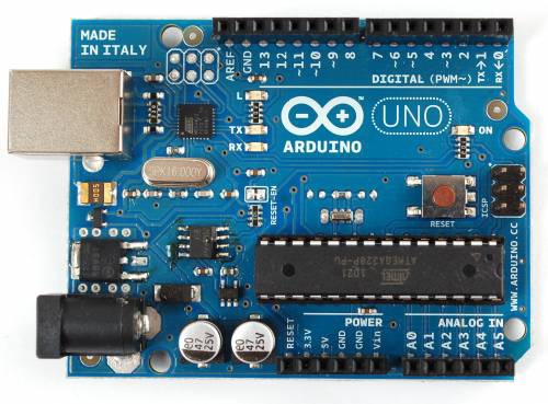
At the bottom of the controller, we have the power connectors that provide 5V power, provide 3.3V power, and provide two ground pins that can be used to ground any components that you attach to the Arduino controller. Power, voltage, and ground are all defined at the end of the book, so if you’re not quite familiar with those terms, then make sure to read it.
Just to the right of the power pins are the Analog In pins. These allow you to receive analog information, that is, information in a range of voltage from 0 to 5V, in 4.9mV (millivolt) increments, which means that the analog information can be between 0 and 1,023. These pins are quite important, because many different types of controls send analog information in a range of values, such as a dial being turned or an infrared sensor sending range information.
Above the analog pins is the processor that the Arduino controller runs. Just above the processor is the reset button. This allows you to restart your program. This is important to know because the controller saves any program uploaded to it. So, if you write a program for your controller that is made to blink an LED on or off, it will begin running that program when you power up the Arduino. The reset button stops the program that is currently running. To change the program saved on the Arduino, you’ll need to clear the memory by uploading a new program. Just to the right of the reset button are the ICSP pins, which allow you to program the Arduino without using the USB cable (handy in some situations).
As a comparison, the Arduino Mini was first introduced in 2006 and is a space-saving alternative to the larger Uno. It can be so much smaller because it uses a different processor package, does not have the same easy-access pins that the Uno has, and requires a USB adapter that can communicate with the computer over USB. That said, the size of the controller means you can use it in projects where space is truly at a premium.
When you turn over the Mini controller, you’ll see a row of small copper pins that represent each pin. These function in the same way as the connectors on the Uno, but where you can simply insert a wire into the Uno, you’ll need to insert the Mini into a prototyping board and then attach a wire to the same line on the board, as shown in Figure 4-10.
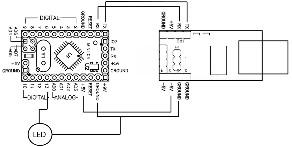
The Mini has 14 digital pins, which, as you can see in the diagram in Figure 4-10, has 8 along the left side of the board and 4 more along the bottom of the right side. Since the pins are not marked on the Mini as they are on the Uno, it’s important to know which pin is which. Above the four digital pins on the right side of the controller are the four analog pins. Unlike the Uno, all of these can be set to read data in or write data out. The other four analog pins (4–7) are at the bottom of the controller in a square-shaped formation.
Next to analog pins 4–7 are a pair of power pins, a ground pin, and a +5V pin to power components. Looking at the Mini, there are 3 +5V power pins and 4 ground pins, one on each side of the board. This makes the Mini even better suited for working in tight places, because grounding pins can be accessed from all sides of the controller, a real blessing when space is at a premium.
For comparison, we’ll take a look at the Arduino Mega now, to show what you can get for a little extra space and battery drain. The Arduino Mega 2560 has 54 digital input/output pins (of which 14 can be used as PWM outputs), 16 analog inputs, 4 UARTs (hardware serial ports), a 16 MHz crystal oscillator, a USB connection, a power jack, an ICSP header, and a reset button. So you have four times the number of PWM pins and analog in pins as the Uno, which makes the Mega a formidable tool for larger systems. You’ll need to consider that it still pushes the same amount of current though, so you won’t be able to drive servos on all those pins without an external power supply.
As of the writing of this book, these are just some of the other Arduino controllers:
- Nano
A compact board designed for breadboard use, the Nano connects to the computer using a Mini USB B cable.
- Ethernet
The Ethernet Arduino controller contains an Ethernet controller and port so that the board can connect to a wired network via Ethernet.
- LilyPad
Designed for wearable application, this board can be sewn onto fabric and is a stylish purple.
- Pro
This board is designed for advanced users who want to leave a board embedded in a project. It’s cheaper than an Uno and easily powered by a battery, but it requires additional components and assembly.
- Pro Mini
Like the Pro, the Pro Mini is designed for advanced users requiring a low-cost, small board and willing to do some extra work.
There are also numerous non-Arduino microcontroller boards that are quite similar to the Arduino: Teensy, Freeduino, Sanguino, Bare Bones Board, LEDuino, and Miduino, among others. The nice thing is that once you’ve learned the basics of using one of these boards, you can apply that knowledge to using any of the others depending on your preference and the particulars of your project.
First, we’ll take a look at the IDE, and then we’ll look at the language that the Arduino controller uses. Looking around the IDE you’ll notice that it’s quite similar to the Processing IDE. This is no accident; the Processing project shared the code and design philosophy for the Arduino IDE, keeping a light, simple, and intuitive design with the IDE.
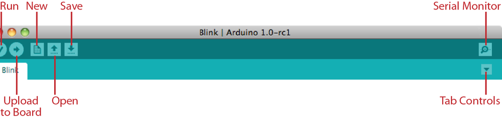
Before discussing the IDE, we’ll explain how Arduino works. In Processing, for example, you compile and then run the code. Arduino adds an extra step to this: you compile the code, but the next step is to upload it to the Arduino controller so you can run it. Your computer doesn’t run Arduino code, so you’ll need to upload your code to a controller that can run the code in order to test what you’ve written. As soon as code is uploaded to the Arduino controller, it runs right away, so the run step of the Processing workflow is entirely removed and replaced by an upload step. Now, take a look at the buttons at the top of the controller (see Figure 4-11).
Clicking the Run button does not in fact run your code; it checks for errors and compiles your code. Still, when you’re writing code, it’s quite handy to know what your errors are before you’ve uploaded anything to the board. The Stop button stops the IDE from listening on the serial port. There’s more information on how this works in the section Debugging Your Application later in this chapter. The New button simply creates a new application, but note that it doesn’t save it automatically. The Open button opens a project from your local machine. The Save button saves your project. The Upload to Board button actually uploads your code to the board, assuming that the board is properly connected and all the drivers are properly installed. Finally, the last button on the right opens the Serial Monitor window. This is quite important if you want feedback from the controller.
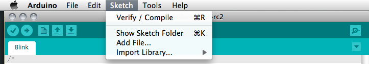
The Sketch menu of the toolbar (shown in Figure 4-12) contains some duplicates of the functionality in the IDE controls but also contains some other interesting options.
The Import Library option allows you to import functionality from a library created for a specific purpose, for instance, working with motors or I2C communication. These can be either the default libraries that come with Arduino or a library that you have created yourself. If you select the Stepper library, for example, you’ll see the following line appear in the code window:
#include <Stepper.h>
This imports the Stepper library into the project, making all of its functionality available to your application. You’ll find more information on importing libraries and functionality later in this chapter. The Show Sketch Folder option is a shortcut that brings up the folder in your operating system (OS) where the application files are stored. This is helpful if you’re storing other files with your application or need to copy or change a file in the file system. Finally, the Add File option allows you to select a file easily from anywhere in your operating system and save it to the folder where your application is located.
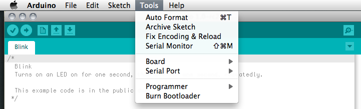
The Tools menu (shown in Figure 4-13) contains menu buttons for selecting the controller and port on which the controller is connected to your computer. Additionally, this menu item contains the Auto Format option, which formats all your code to standardize the indentations and spacing. It also contains a Copy for Forum option, which copies all the code in an application to the system clipboard of your computer in an HTML-ready format so that it can be pasted into a web page without losing its formatting. The Archive Sketch option simply creates a .zip file of your application. Finally, the Burn Bootloader option is a rather advanced topic. Suffice to say that you won’t need to burn a bootloader with any of the controllers that we’ll be looking at unless you’re building your own board.
So, now that we’ve examined the basics, let’s start writing some code. The code window is the main window of the IDE, which is where all your code will go. Once you’ve written something, you’ll want to compile the code, which you can do by clicking the Run button. Give the code in Example 4-1 a spin.
Example 4-1. blink.ino
void setup() {
    pinMode(13, OUTPUT);      // sets digital pin 13 as output
}

void loop() {
    digitalWrite(13, HIGH);
    delay(500);
    digitalWrite(13, LOW);
    delay(500);
}
For those of you with Uno controllers, if there are no errors, you can click the button to upload the code to your board. You should see the TX and RX lights on your controller blink as the code is being uploaded and the memory for the program initialized, and you’ll then see a message displayed in the Console window of the IDE that says something like this:
Binary sketch size: 1092 bytes (of a 14336 byte maximum)
If that works, you’ll see the LED on your board start blinking, and you’re ready for the next section. If it doesn’t, your controller is probably not connected properly. Check the settings for your controller and the port in the Arduino IDE, and try again.
We’re going to jump into code now rather than wiring for one simple
reason: you’ve already seen code, so what you learned in the previous
chapter will help you understand the new things in this chapter. In fact,
the Arduino language is structured quite similarly to the Processing
language with regard to how the application itself is structured. There is
a setup() statement, and code within
that statement runs once when the application first starts up. Then there
is a loop() statement, which runs over
and over again. Almost all Arduino applications consist of the declaration
of some variables that will be needed throughout the lifetime of the
application, one-time initialization to set things up ready to run, and
functions to use in the main loop.
The setup() statement is the
first thing called in the Arduino application. As in a Processing
application, this is where things that need to be initialized should be
placed. For instance, if you’re going to use the serial port for
debugging your application, you’ll need to start the serial connection
using the Serial.begin() method in
the setup() method. Some devices need
to be initialized when the microcontroller starts up; other devices need
to have a signal sent to them just after the device starts up but before
it’s used. These are the sorts of tasks that should be handled in the
setup() statement. All applications
must have a setup() method, even if
nothing is done in them. This is because the compiler will check for
this method, and if it isn’t defined, an error will occur.
The loop() method contains
anything that needs to happen repeatedly in the application; that could
be checking for a new value from a control, sending information to a
computer, sending a signal to a pin, or sending debug information. Any
instructions in this method will be run repeatedly until the application
is terminated. Usually we want to check any values that might be input
from a control or another program, determine what to do with the input,
and then send any information or instructions to any other components or
programs that might need them. We’ll look at two examples, one simple
and one more complex.
In Figure 4-14, you’ll see the organization of the code for a simple program to turn a light on and off when a button is pressed. There are three distinct elements to this program:
initializationThis element contains all the variables and values that will be used throughout the program. Recall that if a variable is declared within a method, then it exists only within that method. This is called variable scope. If this doesn’t sound familiar, take a look back at Chapter 2.
setupThis element contains the code to configure the pin for the button to receive information from a control and set the pin for the light to send information.
loopThis element contains the code to check the value of the button. If it is sending a LOW signal, that is, if the button is pressed, then send a signal to the light to turn on; otherwise, it tells the light to turn off.
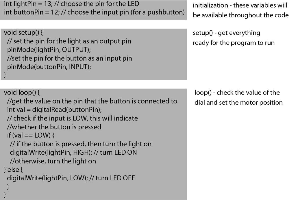
Figure 4-15 shows how an Arduino application breaks these elements down.
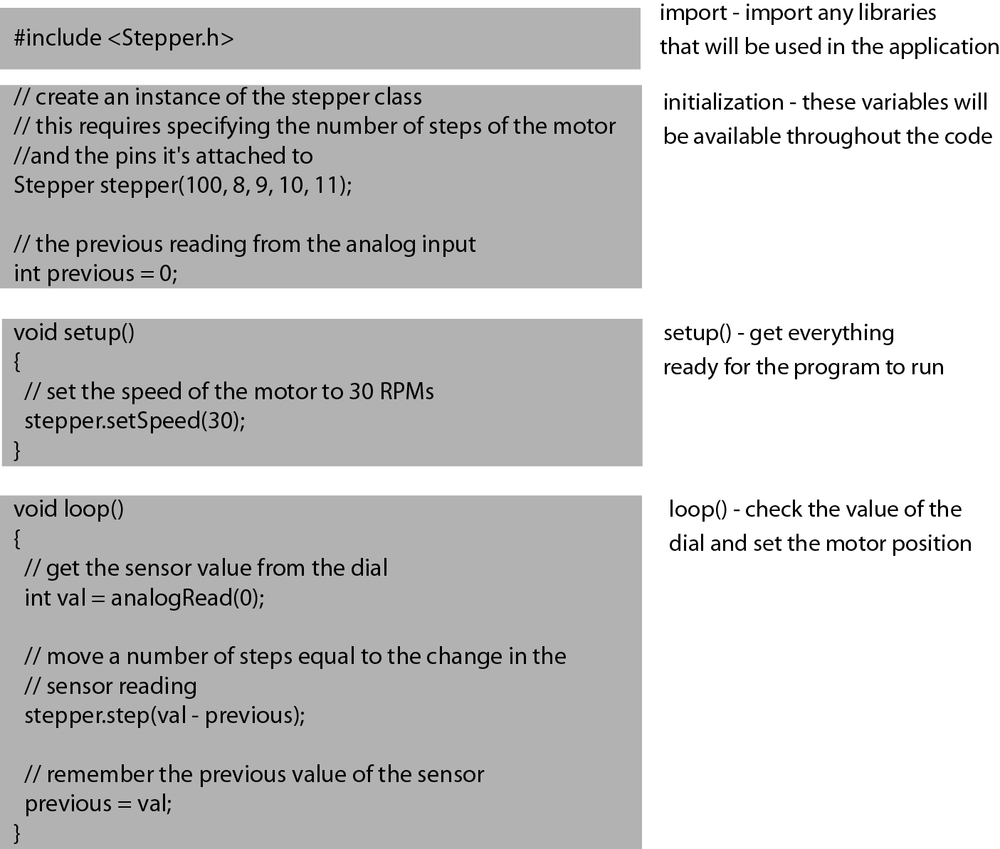
Another, slightly more complex example is to use a potentiometer
(more commonly but less accurately called a dial) to set the position of
a stepper motor. Stepper motors are covered in much greater detail later
in this chapter and in Chapter 11, but for
the moment, think of a stepper motor as being a motor that has distinct
positions that it can be placed at, rather than a simple motor like a
fan that simply spins. To use a stepper motor in Arduino, import the
Stepper library into the application.
Once again, you’ll learn more about importing libraries into an Arduino
application later in this chapter; for the moment, we want to
familiarize you more with the structure of an Arduino application. So
our steps for this application will be as follows:
import: before you do anything else, you need to import any libraries that you’ll use in the application.initialization: this initializes the variables, which in this case includes theStepperobject that you’ll use to handle positioning the stepper motor correctly.setup: this sets the speed of theStepperobject.loop: this checks the value of the dial and sets the position of the stepper motor accordingly.
Figure 4-16 shows the organization of a more complex Arduino application.
The Arduino language is designed to support communication with electronic components. It works in a similar way to Processing, but it is structured a little bit differently because it deals with different problems. When dealing with electrical components, you are usually sending information as voltage or, in the case of I2C, sending communication in binary strings. Still, these forms of communication are at the very root and core of computing; they are, to use two very geeky terms, low level and close to the metal. When one sends an instruction as a pattern of electrical bursts, they’re really working at the level that electrical components speak rather than asking a higher-level or more abstract programming language to do it for them.
The language that Arduino uses is essentially C++. Now, a quick word on C++ is relevant here because it’s important to understand what C++ is and how Arduino is and isn’t like C++. C++ is an old programming language, which makes it very well suited for our purposes because it was designed back when computing memory and processing power were at a premium. This means that while C++ may not be friendly to read and write for the new programmer, it certainly is stingy with its resources, making it perfect for doing things on a microcontroller where resources are more limited than on a desktop machine or laptop. The Arduino language relationship with C++ is quite similar to the relationship that the Processing language has with Java. If you understand C++, you’ll understand a lot of Arduino, and conversely, if you understand Arduino, you’ll understand some C++. Now, it’s important to note that Arduino is not quite C++, which is to say that if you find some neat C++ code somewhere that you want to run, pasting it into the Arduino IDE and expecting it to work might lead to disappointment. You can do this, but it requires some planning and some serious knowledge of what you’re doing.
The basics of the Arduino programming language are similar to C++ and Processing. Methods are defined with a return type and any parameters like so:
return methodName(params...) {}Variables are defined like so:
variableType variableName;
Some of the other features of the Arduino language aren’t going to be so immediately familiar, but the next few paragraphs will help explain some of the more important ones.
The Arduino language has the following constant variables that can be used throughout any Arduino application:
true/falseYou can always use
trueandfalsejust as they are. These are predefined, never change, and are always available:if(variable == true) { doSomething(); } else { doSomethingElse(); }HIGH/LOWThese define the voltage level on a digital pin, either 5V or 0V. These make your code more readable:
digitalWrite(13, HIGH);
INPUT/OUTPUTThese are constants used for setting pins that can be used either for output or for input:
pinMode(11, OUTPUT);
As you’ll notice, the
OUTPUTconstant is used to set the value of the pin using thepinMode()method. This seems like a good place to segue into the core methods of the Arduino language.
Now you should learn about some of the methods of the Arduino language:
pinMode(pinNumber,
          mode)
Remember that the digital pins of the Arduino controller can be set to either input or output, which is to say that they’ll send values to a controller or receive values from a controller. Before we use a digital pin, though, we need to establish in which direction the information on that controller will be flowing. Usually you do this in the
setup()method, because you’ll rarely need to do it more than once in an application.digitalWrite(value, pin)This method sets a digital pin to
HIGHif value is high orLOWif value is low, which is to say that it sends 5V or 0V through the pin. This can work only on pins that have been set toOUTPUTusingpinMode(). For example:pinMode(11, OUTPUT); digitalWrite(11, HIGH);
If the
pinMode()method hasn’t been used to set the pin to beOUTPUT, then callingdigitalWritewill have no effect.int digitalRead(pinNumber)This method reads the state of a pin that is in input mode. This can be either
HIGHorLOW, that is, 5 V or 0 V, and no other value. ThedigitalReadmethod is used for reading buttons, switches, anything that has a simple on and off, and any control that returns a simpletrueorfalse,1or0, or other type of binary value. It returns the value of the pin read as an integer.analogRead(pinNumber)This reads the value of an analog pin, returning a range from 0 to 1,023, that represents the voltage being passed into the pin. As you’ll discover later, it is important that any controllers you connect to your Arduino controller send analog signals in the range between 0 and 5 V because higher values will not be read and could damage the board. This method returns an integer and so can be used as shown here:
int analogVal = analogRead(11);
This code snippet uses the value returned from the
analogReadmethod and stores it in theanalogValinteger. This is a common technique that allows you to retrieve the value from a pin and use that value later in your code.analogWrite(pin, value)This writes an analog value to a pin and can be any value between 0 and 255. This means that the value sent to this method can be used as an adjustable voltage and sent through the pin to any controller on the side:
analogWrite(11, 122);
delay(ms)This method tells the program to wait for a given number of milliseconds before executing the next instruction. In practice, this means that in the following lines of code:
digitalWrite(13, HIGH);
delay(1000);
digitalWrite(13, LOW);
there will be a delay of one full second between when the first instruction and the third instruction are executed. In practice, this is often used for timing, such as controlling how long, for example, a light stays lit.
millis()This returns the number of milliseconds since the program started running. This can be useful if you need to keep track of time, which you can do by storing the result of the
milliscall and then comparing with anothermilliscall at some later point, as shown here:long timer = 0; void setup() { timer = millis();// get the timer the first time } void loop() { int lengthOfALoop = millis() - timer; // compare it timer = millis(); // now set the timer variable again }Of course, you might want to do something more interesting with
millis, but it’s a start.
Arduino treats arrays in much the same way as C++ and somewhat like Processing, though you cannot use the constructor with an array as with Processing. The same rules about what can be stored in the array apply:
int intArray[10]; // now the array is ready, no need to call new Array()
intArray[4] = 4;
intArray[3] = "hello!"; // doesn't work!
You can also declare and initialize an array at the same time:
int preinitialized[3] = {1, 2, 3};Working with strings in Arduino is different from working with
strings in Processing or openFrameworks because the Arduino language
doesn’t use a String class like C++ and Processing. This might seem
like a big deal at first, but you’ll realize after working with Arduino
for a little while that the types of things that you do with Arduino
don’t require strings or text as frequently. If you do need to work with
a String class, you need to make an
array of characters, as shown here:
char name[5] = {'j', 'o', 's', 'h', 0};or
char name[] = "josh";
If you need to, for example, store multiple strings in an array,
you can create an array with multiple char arrays stored within it:
char* multichar[4];
char name1[5] = {'j', 'o', 's', 'h',0};
char name2[5] ={'t', 'o', 'd', 'd',0};
or
char * multichar[] = {"josh", "todd"};OK, so what’s going on here? You’ll notice that there’s a pointer
being used in a somewhat non standard way to store the arrays. Pointers
are covered in greater detail in Chapter 5. When you declare the array, you’re
declaring that it will store pointers to char
variables. Though this may seem a little strange at first, it isn’t hard
to get used to, and generally, in Arduino, you’re not dealing very
extensively in Strings.
Of course, the one thing that we haven’t talked about much yet is how to actually connect things to your board. To connect a component to your board, you need to create an electrical connection between the correct pin on your board and the correct corresponding pin on the component. There are two ways of getting this done: using a project board and solder or using a prototyping board.
Soldering should be used once your designs are really ready. Prototyping boards save time and solder because they allow you to fix mistakes easily. Just pop the wires out, and connect them in the right place; it’s much easier than needing to undo a bunch of solder and resolder it all. There are lots of situations in electronics where you don’t want to use a prototyping board because they can allow stray current to leak around places you might not want it, but since the controller of the Arduino is already somewhat protected, a breadboard is fine to use. Figure 4-17 shows a prototyping board.
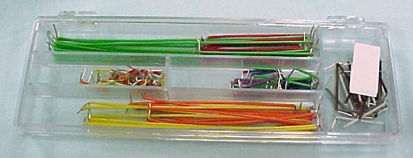
To connect the controller to the board, you can use either solid 24-gauge wire or jumper wires like the kind shown in Figure 4-18.
Both the prototyping board and the wires can be procured from an electronics store and will make your Arduino experimenting life a lot easier. A prototyping board has two different directions for its rows. The rows on the edge of the board travel the length of the board, as you can see in Figure 4-19.
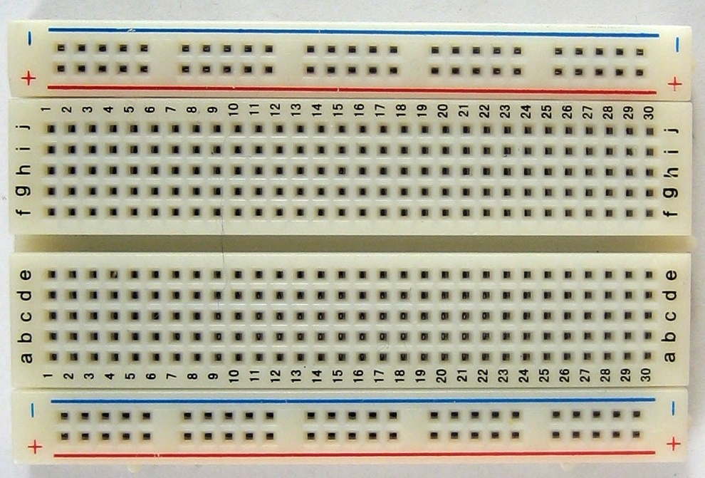
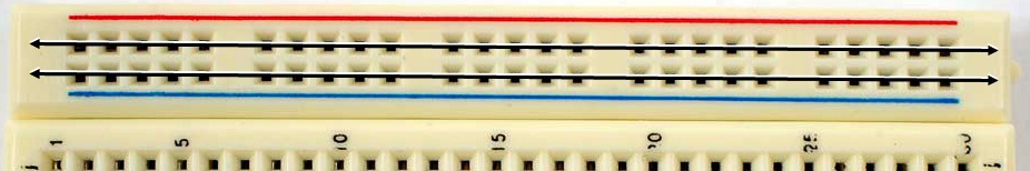
The top two rows are usually used with one row providing access to power for all components and the other providing a ground for all components on the board. The middle of the board is a little different, as shown in Figure 4-20.
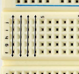
The middle of the board is where you connect components and controllers together. Each row can be connected to the others using either 24-gauge wire or jumper wires. Connecting two rows together makes them share a circuit.
Once you have your design ready to go, you can easily pick up a drilled breadboard, some solder, and a soldering iron and get started making a more permanent version of your project. Until then, though, it’s easier to use the prototyping board. There’s one more thing you’ll need to connect things to your board: a resistor.
The resistor is one of the most important electrical components that you’ll use, and for that reason we should explain why they get their own section. Resistors do one thing: resist the flow of electrical current, hence the name resistor. By resisting current, not letting it flow, they control where and how fast electrons flow.
Everyone, from high school physics teachers to electrical engineers, uses the current-as-water metaphor, and for consistency sake, I’m going to stick with it. Imagine that electrical current is water, a stream flowing along. Now imagine that you force the water through a pipe that is slightly smaller than the stream bank. This will cause some of the water to not get through; you’ll be limiting the amount of water flowing. Smaller the pipe, the less water gets through. This, in essence, is the resistor. The resistor only allows a certain amount of the electrical current to pass through it. It has a special relationship to the voltage and the current that you’ll see a little farther down the page. To continue with our water metaphor: with a fire hydrant, you want low resistance, with a water fountain, you want high resistance. Mix up the two pipe sizes and you can’t put out a fire and hurt yourself trying to get a small sip of water. Most electrical components are the same: they can only handle certain amounts of current or they use certain amounts of current to signal states or modes. Resistors are the way to do both of these.
Now we move on to the more scientific explanation. Resistance is measured in ohms, written as the Omega symbol Ω. The larger the resistance value, the less current it allows. Resistors generally range from 1 ohm at the smallest to 1 mega-ohm (1.0 MΩ) at the largest. You can read the resistor by looking at the colored stripes on the body of the resistor, called the resistor color code, but they’re difficult to understand at first. Luckily a quick online search will show you mobile phone apps, reference tables, calculators, and other tools to help you understand which resistor you have in your hand.
Now the math: the ratio of the voltage applied across resistor’s terminals to the intensity of current flowing through the resistor is called resistance. This relation is represented with something called Ohm’s law:
voltage = current * resistance
often written as
V = IR
That means that the current can be found by dividing the voltage by the resistance.
I = V/R
LEDs can only handle certain amounts of current. The 5V of your Arduino passed through a 1K ohm resistor means that there are 0.005 amps passing through the LED. That’s perfectly safe for the LED. Allow more current to pass through and the LED will burn out, allow less and it will glow less brightly. There’s more to know about resistors, but we’ll leave it at that for the moment.
The “Hello World” of the Arduino controller is a blinking light. For this to work, you’ll need to do your first little bit of wiring with the Arduino controller, attaching an LED to pin 13 of your controller with a 5K resistor as shown in Figure 4-21. To get this to work properly, you’ll need to add a new element to the wiring scheme, the 1k resistor. We’re using the resistor to prevent the Arduino from burning out the LED, since the Arduino can send more current than an LED can handle.
Once you’ve attached the pin to the controller, put the following in the code window of the IDE, and click Run. After the IDE has finished compiling the code, click Upload. It should take a few seconds to upload the code to the controller, and then you should see the LED blink on and then off in a syncopated rhythm.
Example 4-2. brightness.ino
int ledPin = 9;
int brightness = 0;
boolean increase;

void setup() // run once, when the application starts
{
  pinMode(ledPin, OUTPUT); // sets the pin where our LED is as an output
  increase = true;
}

void loop() // run over and over again
{
  if(increase)
    brightness++;
  else
    brightness--;

  if(brightness == 1023 || brightness == 0)
    increase != increase;

  analogWrite(ledPin, brightness);   // sets the LED on
}
That’s not too exciting yet, is it? In the spirit of interactivity,
let’s give you some control over that LED. We’re going to use the INPUT mode of the pin that a button is connected
to so we can send a signal and control the LED with the button, as shown
in Example 4-3.
Example 4-3. buttonOn.ino
int lightPin= 13; // choose the pin for the LED
int buttonPin = 10;   // choose the input pin (for a pushbutton)

void setup() {
    // set the pin for the light as an output pin
    pinMode(ledPin, OUTPUT);
    // set the pin for the button as an input pin
    pinMode(buttonPin, INPUT);
}

void loop() {
    // get the value on the pin that the button is connected to
    int val = digitalRead(buttonPin);
    // check if the input is LOW, this will indicate
    // whether the button is pressed
    if (val == 0) {
        // if the button is pressed, then turn the light on
        digitalWrite(lightPin, HIGH);  // turn LED ON
        // otherwise, turn the light on
    } else {
        digitalWrite(lightPin, LOW);  // turn LED OFF
    }
}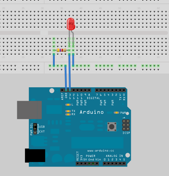
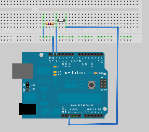
When the circuit is completed, flowing all the way through, the value from pin 10 will read LOW, and the light will be given power to turn it on. Create the circuit in Figure 4-21.
This is where using a breadboard pays off. Plug the +5V pin into one of the connection lines that runs the length of the board and a ground pin into the other connection line. Next, use the 10K resistor to create a connection between one pin of the button and the connection line that carries the 5V. The button will have two connection points, so one gets connected with the resistor and the other gets connected to the ground connection line. Then, connect the LED to the ground connection line and pin 13. Take a look at Figure 4-22.
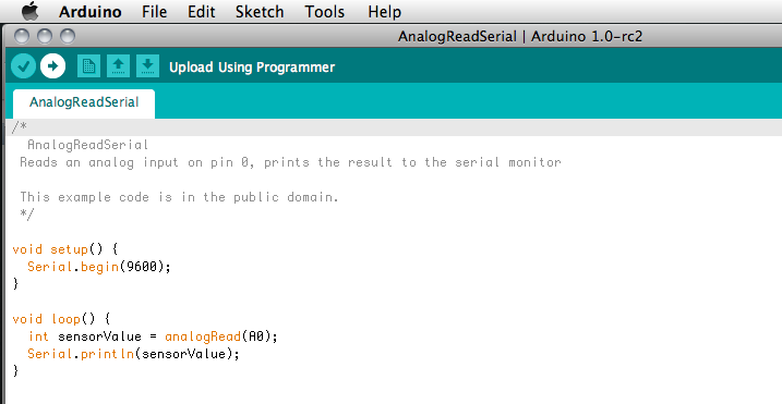
To upload the code, simply click the Upload button, as shown in Figure 4-23.
You should see the LEDs on the board begin flashing, and you should see a message printed out in the console window. Your Arduino controller may take a second or two to begin running the code, but you’ll be able to turn the light on and off.
So, what do we do if we need to know the value being sent back from
a sensor to a controller? Or, what if there’s something going wrong that
you can’t quite sort out? You’ll use the Serial library to send
messages—character strings actually—back from the controller to the
computer so you can see what’s happening. This lets you send messages to
know that something is working or not working and to monitor the values
being passed around in your application. Whenever you have some code that
you need to monitor, you can use the Serial
print() method to allow you to check the values of variables or
the execution of code and see those messages in real time using the Serial
window of the Arduino IDE.
Use the begin() method of the
Serial class in the setup() method of your application to set the
communications speed:
int speed = 9600;

void setup() {
    Serial.begin(speed)
}
This sets the data rate in bits per second (baud) for serial data
transmission. For communicating with the computer, use one of these rates:
300, 1200, 2400, 4800, 9600, 14400, 19200, 28800, 38400, 57600, or 115200.
The higher the number, the faster the Arduino controller will send
messages to the computer, but also the higher demand you’ll make on your
controller. Note, too, that the speed needs to be the same on the sending
and receiving, so if you’re trying to read data on the Serial Monitor of
your Arduino IDE, you’ll need to make sure that you’re using the same
speed in the IDE as you’ve set in the begin() method. Once you’ve called the begin() method of the serial, you can send data
from your Arduino controller to your computer using the print() method:
Serial.print(data)
The print() method is more or
less like the Processing print() method
that you encountered in Chapter 3 and the printf() you’ll encounter in Chapter 6, but it is optimized to save space for Arduino
and so works slightly differently. By default, the print() method, with no format specified, prints
an ASCII string. For example, the following:
int b = 79;
Serial.print(b);
prints the string 79 to the
Serial Monitor window. The little application in Example 4-4 will print the message every two
seconds.
Example 4-4. serialTalking.ino
int i = 0;
void setup() {
Serial.begin(9600);
}
void loop() {
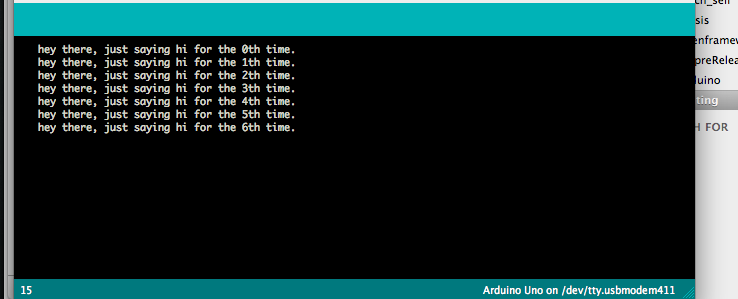
Serial.print(" hey there, just saying hi for the ");
Serial.print(i);
Serial.print("th time. \n");
delay(2000);
i++;
}Once you’ve uploaded the application to the board, you start monitoring the output of the serial by clicking the Serial Monitor button, as shown in Figure 4-24.
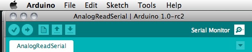
Once the Serial Monitor is started, you can see the output in the bottom of the Arduino IDE, as in Figure 4-25.
You’ll need to make sure that the baud rate selected in the
drop-down list above the output window matches the rate that you passed to
the serial begin() method, or the
Serial Monitor won’t be listening at the same rate that the controller is
sending.
You can also pass additional parameters to the print() method to get the output to be formatted
a specific way:
int b = 79;
Serial.print(b, HEX);
This prints the string 4F, which
is the number 79 in hexadecimal. Table 4-1 lists most of the
format specifiers for the serial print() method.
Table 4-1. Output with the serial print() method
Format specifier | Output |
|---|---|
DEC | Prints the value as an decimal |
HEX | Prints the value as a hexadecimal |
OCT | Prints the value as an octal value |
BIN | Prints the value as a binary number |
BYTE | Prints the value as a single byte using ASCII characters |
(No format specified) | Prints the value as a string |
There are many extremely useful libraries for the Arduino controller that help you do things like work with LED lights, control motors, use LCD screens, or even control certain kinds of cell phones.
For this section, we’ll primarily use the Stepper library for demonstrations. The Stepper library comes with the Arduino download and allows you to reduce the number of connections required by a stepper motor from four to two. We won’t get into why this is good and what this allows us to achieve in any great detail until Chapter 8, focusing here instead on how the library functions in the Arduino environment.
An Arduino library is generally made up of four parts:, an .h file, a .cpp file, a keywords.txt file that highlights Arduino
library words in the IDE, and the actual binary library code. Arduino uses
.h files to contain the information
about a library, the variables it contains, the methods that it has, and
so forth. The .cpp file contains the
definitions for those methods and variables and is compiled into the
binary library files used at runtime by the Arduino controller. For those
of you experienced working with C or C++ already (which, after you read
through the sections on openFrameworks, will be all of you), you’ll
recognize the .h file and what it
does. The .h file is what is imported
into the Arduino application using the #include statement. If you want to know what is
in a library, glancing at the .h file
will tell you. For example, looking at the Stepper.h
file, you’ll see the following:
// constructors:
Stepper(int number_of_steps, int motor_pin_1, int motor_pin_2);
Stepper(int number_of_steps, int motor_pin_1, int motor_pin_2, ¬
    int motor_pin_3, int motor_pin_4);
// speed setter method:
void setSpeed(long whatSpeed);
// mover method:
void step(int number_of_steps);
int version(void);
This tells you that to create a new instance of the stepper, you
pass it the number of steps, the pin that the first motor is connected to,
and the pin to which the second motor is connected. Once you’ve created
the stepper, you can call two methods on it: setSpeed() and step(). Learning to read .h files is a great asset in working with
Arduino, openFrameworks, C, and C++, because it saves you the time of
digging through documentation, and helps you get acquainted with the inner
workings of the programming languages and the libraries that are written
in them. There will be plenty more on .h files later
on in this book.
So, now that you’ve had a crash course in .h files, you’ll look at importing some functionality. It’s actually quite simple; you add the following line to the top of the application file:
#include <Stepper.h>
This will import all the stepper functionality, allowing you to
create new Stepper objects and call
their methods. For instance, take Example 4-5.
Example 4-5. stepper.ino
#include <Stepper.h>

Stepper stepper(100, 8, 9, 10, 11); // note that we don't use = new Stepper();

void setup()
{
    // set the speed of the motor to 50 RPM
    stepper.setSpeed(50);
}

void loop()
{
    stepper.step(1);
    delay(500);
    stepper.step(2);
    delay(500);
    stepper.step(2);
    delay(500);
}
The Arduino download comes with a few core libraries that we’ll outline in a rough way, just to give you an idea what’s out there:
- EEPROM
Depending on the board, the microcontroller on the Arduino board has 4 kilobytes, 1 kilobyte, or 512 bytes of EEPROM, which is permanent memory, like an extremely small hard drive that you can save information to. So, how big is 512 bytes? It’s 128 integers, or 512 Boolean values; so it’s not a lot, but it’s enough.
So, you ask what you might do with it. You can save the last values input by a user, save the last state of a controller, save the highest reading ever for a component, save just a tiny bit of GPS data, or store a URL or some other kind of valuable information.
- Stepper
This library allows you to control stepper motors. To use it, you will need a stepper motor and the appropriate hardware to control it.
What you might use it for: making things that use stepper motors, of course, such as making small robot arms, rotating cameras, manipulating toys, pointing things, or driving things.
- Wire
Two-Wire Interface (TWI/I2C) is for sending and receiving data over a net of devices or sensors. This library allows you to communicate with I2C/TWI devices. On the Arduino, SDA (data line) is on analog input pin 4, and SCL (clock line) is on analog input pin 5.
So, you ask what you might use it for. You can read GPS sensors, read from RFID readers, control accelerometers, and in fact do many of the things that we’re going to do later in this book.
Once you have loaded your program onto the board, it is saved in the program memory of the board whether the board is being powered or not. There’s no worry about the controller forgetting its program. When the controller starts up again, it will automatically run the last program that it had loaded into it.
You can clear the RAM memory of the board either by grounding the reset pin, which works on the Uno and the Mini, or by simply pressing the reset button, which works only on the Uno. This restarts the board and the program that is saved on the board, but doesn’t clear the program. That will happen only when a new program is uploaded to the board.
There are two ways to run your Arduino, both of which are available to you with the Uno controller, and one of which is available to you with the Mini controller. The first is to plug the controller directly in to a wall using a 9V or 12V DC adapter, and this can be done only with the Uno. Most electronics supply shops will have one of these adapters with the correct attachment end that will fit in the Uno DC port.
The other option, which is available on both controllers, is to simply use a 9V battery with a snap-on cap that allows you to get two wires from the battery to send to the controller. On the Mini, attach the positive lead (the red wire) of the battery cap to the +9V pin and the ground lead (the black wire) of the battery cap to the ground pin. On the Uno, attach the positive lead to the 9V Voltage In (Vin) pin and the ground lead to the ground pin. You’re now wireless and free to wander around with your Arduino.
Warning
When connecting to a power source, be careful. You can fry your controller by sending voltage to the wrong pin. If working with a battery, always connect the ground first and the positive lead after.
You’ve seen the beginnings of the Arduino; now you can either flip ahead to Chapter 8, where you will work with the Arduino to create some real interactivity, or you can read the next chapter, which delves a little deeper into programming to get you ready for openFrameworks and C++.
The Arduino project is several different components: a microcontroller board, a simplified version of C and C++ for nonengineers to use in programming their microcontroller, and an IDE and compiler used to create and load code onto the microcontroller board.
To get started with the Arduino, you’ll need to download the Arduino IDE and compiler from the http://arduino.cc website and purchase a board from one of the online suppliers.
Once you have the board and the IDE ready, you’ll need to configure the IDE correctly for your board by plugging the board in and then, in the IDE, going to the Tools menu, selecting the board option, and selecting the board that you’re using.
You can run a simple blinking light script to ensure that your board is working properly.
Pins can either input, which means they will read values from a control, or output values to a control. Communication between the Arduino and any controls attached to it is done via the amount of voltage being sent either to or from the Arduino. Arduino controllers have two kinds of pins: analog pins that can read and write analog values, from 0 to 5V, and digital pins that simply read or write binary values represented as 0V or 5V.
Running an Arduino program has two steps: the first is to compile the code on your computer in the Arduino IDE. You can do this by pressing Ctrl-R (⌘-R on OS X). Once your code compiles, you upload it to the Arduino board using the Upload to I/O Board button on the Arduino IDE or by pressing Ctrl-U (⌘-U on OS X).
An Arduino application has two required methods: the setup() method that is called once when the
application first starts up, and the loop() method that is called over and
over.
To attach an LED to your Arduino, connect the first lead of the LED
to a resistor, connect the resistor to any digital pin, and connect the
second lead of the LED to Ground. Once you use the digitalWrite() method to set that pin to
HIGH, the LED will light up.
To connect a button to your Arduino, attach a button with a resistor to a digital pin and the other end of the button to the 5V pin of the Arduino. Buttons are an easy way to get started creating some physical interactivity in your designs.
To debug your application, you can use the Serial.print() method to send messages from your
Arduino controller to the console of the Arduino IDE at critical junctions
to help you see what your application is doing.
The Serial.print() method can be
formatted by passing a second parameter to the print() method to specify what format should be
used.
You can import libraries to your Arduino application using the Sketch menu item of the toolbar at the top of the Application menu and then selecting the Import Library option. You can also write the name of the .h file that the library uses, if you’ve placed it in the libraries folder of your Arduino installation, like so:
#include <Wire.h>
Other Arduino libraries allow you to work with stepper motors, Two-Wire Interface, the memory of the Arduino controller, and many other techniques or controls.
Once you’ve written a working program and have uploaded it to the Arduino, the board will save the code in program memory and begin executing the program. The code will start as soon as the board is powered up again.
Get Programming Interactivity, 2nd Edition now with the O’Reilly learning platform.
O’Reilly members experience books, live events, courses curated by job role, and more from O’Reilly and nearly 200 top publishers.

