I consider that the golden rule requires that if I like a program I must share it with other people who like it. Software sellers want to divide the users and conquer them, making each user agree not to share with others. I refuse to break solidarity with other users in this way. I cannot in good conscience sign a nondisclosure agreement or a software license agreement. So that I can continue to use computers without dishonor, I have decided to put together a sufficient body of free software so that I will be able to get along without any software that is not free.
In this chapter, weâll examine the steps involved in preparing your software for execution on an embedded system. Weâll also discuss the associated development tools and see how to build the Blinking LED program shown in Chapter 3.
But before we get started, we want to make it clear that embedded systems programming is not substantially different from the programming youâve done before. The only thing that has really changed is that you need to have an understanding of the target hardware platform. Furthermore, each target hardware platform is uniqueâfor example, the method for communicating over a serial interface can vary from processor to processor and from platform to platform. Unfortunately, this uniqueness among hardware platforms leads to a lot of additional software complexity, and itâs also the reason youâll need to be more aware of the software build process than ever before.
We focus on the use of open source software tools in this edition of the book. Itâs wonderful that software developers have powerful operating systems and tools that are totally free and are available for exploring and altering. Open source solutions are very popular and provide tough competition for their commercial counterparts.
When build tools run on the same system as the program they produce, they can make a lot of assumptions about the system. This is typically not the case in embedded software development, where the build tools run on a host computer that differs from the target hardware platform. There are a lot of things that software development tools can do automatically when the target platform is well defined. [1] This automation is possible because the tools can exploit features of the hardware and operating system on which your program will execute. For example, if all of your programs will be executed on IBM-compatible PCs running Windows, your compiler can automateâand, therefore, hide from your viewâcertain aspects of the software build process. Embedded software development tools, on the other hand, can rarely make assumptions about the target platform. Instead, the user must provide some of her own knowledge of the system to the tools by giving them more explicit instructions.
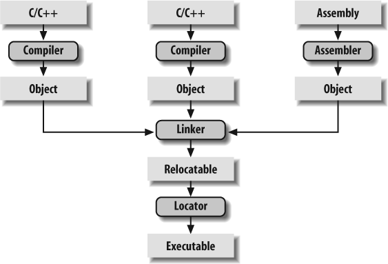
The process of converting the source code representation of your embedded software into an executable binary image involves three distinct steps:
Each of the source files must be compiled or assembled into an object file.
All of the object files that result from the first step must be linked together to produce a single object file, called the relocatable program.
Physical memory addresses must be assigned to the relative offsets within the relocatable program in a process called relocation.
The result of the final step is a file containing an executable binary image that is ready to run on the embedded system.
The embedded software development process just described is illustrated in Figure 4-1. In this figure, the three steps are shown from top to bottom, with the tools that perform the steps shown in boxes that have rounded corners. Each of these development tools takes one or more files as input and produces a single output file. More specific information about these tools and the files they produce is provided in the sections that follow.
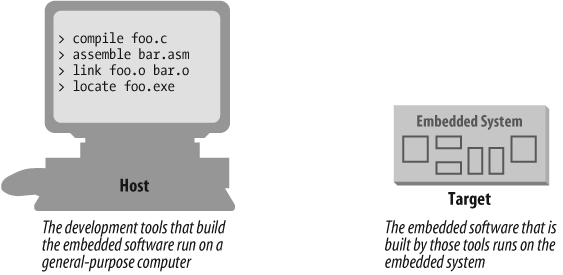
Each of the steps of the embedded software build process is a transformation performed by software running on a general-purpose computer. To distinguish this development computer (usually a PC or Unix workstation) from the target embedded system, it is referred to as the host computer. The compiler, assembler, linker, and locator run on a host computer rather than on the embedded system itself. Yet, these tools combine their efforts to produce an executable binary image that will execute properly only on the target embedded system. This split of responsibilities is shown in Figure 4-2.
In this book, weâll be using the GNU tools (compiler, assembler, linker, and debugger) for our examples. These tools are extremely popular with embedded software developers because they are freely available (even the source code is free) and support many of the most popular embedded processors. We will use features of these specific tools as illustrations for the general concepts discussed. Once understood, these same basic concepts can be applied to any equivalent development tool. The manuals for all of the GNU software development tools can be found online at http://www.gnu.org/manual.
The job of a compiler is mainly to translate programs written in some human-readable language into an equivalent set of opcodes for a particular processor. In that sense, an assembler is also a compiler (you might call it an âassembly language compilerâ), but one that performs a much simpler one-to-one translation from one line of human-readable mnemonics to the equivalent opcode. Everything in this section applies equally to compilers and assemblers. Together these tools make up the first step of the embedded software build process.
Of course, each processor has its own unique machine language, so you need to choose a compiler that produces programs for your specific target processor. In the embedded systems case, this compiler almost always runs on the host computer. It simply doesnât make sense to execute the compiler on the embedded system itself. A compiler such as thisâthat runs on one computer platform and produces code for anotherâis called a cross-compiler. The use of a cross-compiler is one of the defining features of embedded software development.
The GNU C compiler (gcc) and assembler (as) can be configured as either native compilers or cross-compilers. These tools support an impressive set of host-target combinations. The gcc compiler will run on all common PC and Mac operating systems. The target processor support is extensive, including AVR, Intel x86, MIPS, PowerPC, ARM, and SPARC. Additional information about gcc can be found online at http://gcc.gnu.org.
Regardless of the input language (C, C++, assembly, or any other), the output of the cross-compiler will be an object file. This is a specially formatted binary file that contains the set of instructions and data resulting from the language translation process. Although parts of this file contain executable code, the object file cannot be executed directly. In fact, the internal structure of an object file emphasizes the incompleteness of the larger program.
The contents of an object file can be thought of as a very large, flexible data structure. The structure of the file is often defined by a standard format such as the Common Object File Format (COFF) or Executable and Linkable Format (ELF). If youâll be using more than one compiler (i.e., youâll be writing parts of your program in different source languages), you need to make sure that each compiler is capable of producing object files in the same format; gcc supports both of the file formats previously mentioned. Although many compilers (particularly those that run on Unix platforms) support standard object file formats such as COFF and ELF, some others produce object files only in proprietary formats. If youâre using one of the compilers in the latter group, you might find that you need to get all of your other development tools from the same vendor.
Most object files begin with a header that describes the
sections that follow. Each of these sections contains one or more
blocks of code or data that originated within the source file you
created. However, the compiler has regrouped these blocks into related
sections. For example, in gcc all
of the code blocks are collected into a section called text, initialized global variables (and
their initial values) into a section called data, and uninitialized global variables
into a section called bss.
There is also usually a symbol table somewhere in the object file that contains the names and locations of all the variables and functions referenced within the source file. Parts of this table may be incomplete, however, because not all of the variables and functions are always defined in the same file. These are the symbols that refer to variables and functions defined in other source files. And it is up to the linker to resolve such unresolved references.
All of the object files resulting from the compilation in step one must be combined. The object files themselves are individually incomplete, most notably in that some of the internal variable and function references have not yet been resolved. The job of the linker is to combine these object files and, in the process, to resolve all of the unresolved symbols.
The output of the linker is a new object file that contains all
of the code and data from the input object files and is in the same
object file format. It does this by merging the text, data, and bss sections of the input files. When the
linker is finished executing, all of the machine language code from
all of the input object files will be in the text section of the new file, and all of the
initialized and uninitialized variables will reside in the new
data and bss sections, respectively.
While the linker is in the process of merging the section
contents, it is also on the lookout for unresolved symbols. For example, if one object file
contains an unresolved reference to a variable named foo, and a variable with that same name is
declared in one of the other object files, the linker will match them.
The unresolved reference will be replaced with a reference to the
actual variable. For example, if foo is located at offset 14 of the output
data section, its entry in the symbol table will now contain that
address.
The GNU linker (ld) runs on all of the same host platforms as the GNU compiler. It is a command-line tool that takes the names of all the object files, and possibly libraries, to be linked as arguments. With embedded software, a special object file that contains the compiled startup code, which is covered later in this section, must also be included within this list. The GNU linker also has a scripting language that can be used to exercise tighter control over the object file that is output.
If the same symbol is declared in more than one object file, the linker is unable to proceed. It will likely complain to the programmer (by displaying an error message) and exit.
On the other hand, if a symbol reference remains unresolved
after all of the object files have been merged, the linker will try to
resolve the reference on its own. The reference might be to a
function, such as memcpy, strlen, or malloc, that is part of the standard C
library, so the linker will open each of the libraries described to it
on the command line (in the order provided) and examine their symbol
tables. If the linker thus discovers a function or variable with that
name, the reference will be resolved by including the associated code
and data sections within the output object file. [2] Note that the GNU linker uses
selective linking, which keeps other unreferenced
functions out of the linkerâs output image.
Unfortunately, the standard library routines often require some changes before they can be used in an embedded program. One problem is that the standard libraries provided with most software development tool suites arrive only in object form. You only rarely have access to the library source code to make the necessary changes yourself. Thankfully, a company called Cygnus (which is now part of Red Hat) created a freeware version of the standard C library for use in embedded systems. This package is called newlib . You need only download the source code for this library from the Web (currently located at http://sourceware.org/newlib), implement a few target-specific functions, and compile the whole lot. The library can then be linked with your embedded software to resolve any previously unresolved standard library calls.
After merging all of the code and data sections and resolving all of the symbol references, the linker produces an object file that is a special ârelocatableâ copy of the program. In other words, the program is complete except for one thing: no memory addresses have yet been assigned to the code and data sections within. If you werenât working on an embedded system, youâd be finished building your software now.
But embedded programmers arenât always finished with the build process at this point. The addresses of the symbols in the linking process are relative. Even if your embedded system includes an operating system, youâll probably still need an absolutely located binary image. In fact, if there is an operating system, the code and data of which it consists are most likely within the relocatable program too. The entire embedded applicationâincluding the operating systemâis frequently statically linked together and executed as a single binary image.
One of the things that traditional software development tools do automatically is insert startup code: a small block of assembly language code that prepares the way for the execution of software written in a high-level language. Each high-level language has its own set of expectations about the runtime environment. For example, programs written in C use a stack. Space for the stack has to be allocated before software written in C can be properly executed. That is just one of the responsibilities assigned to startup code for C programs.
Most cross-compilers for embedded systems include an assembly language file called startup.asm, crt0.s (short for C runtime), or something similar. The location and contents of this file are usually described in the documentation supplied with the compiler.
Startup code for C programs usually consists of the following series of actions:
Disable all interrupts.
Copy any initialized data from ROM to RAM.
Zero the uninitialized data area.
Allocate space for and initialize the stack.
Initialize the processorâs stack pointer.
Call
main.
Typically, the startup code will also include a few
instructions after the call to main. These instructions will be executed
only in the event that the high-level language program exits (i.e.,
the call to main returns).
Depending on the nature of the embedded system, you might want to
use these instructions to halt the processor, reset the entire
system, or transfer control to a debugging tool.
Because the startup code is often not inserted automatically, the programmer must usually assemble it himself and include the resulting object file among the list of input files to the linker. He might even need to give the linker a special command-line option to prevent it from inserting the usual startup code. Working startup code for a variety of target processors can be found in a GNU package called libgloss .
The tool that performs the conversion from relocatable program to executable binary image is called a locator. It takes responsibility for the easiest step of the build process. In fact, you have to do most of the work in this step yourself, by providing information about the memory on the target board as input to the locator. The locator uses this information to assign physical memory addresses to each of the code and data sections within the relocatable program. It then produces an output file that contains a binary memory image that can be loaded into the target.
Whether you are writing software for a general-purpose computer or an embedded system, at some point the sections of your relocatable program must be assigned actual addresses. Sometimes software that is already in the target does this for you, as RedBoot does on the Arcom board.
In some cases, there is a separate development tool, called a locator, to assign addresses. However, in the case of the GNU tools, this feature is built into the linker (ld).
The memory information required by the GNU linker can be passed to it in the form of a linker script. Such scripts are sometimes used to control the exact order of the code and data sections within the relocatable program. But here, we want to do more than just control the order; we also want to establish the physical location of each section in memory.
What follows is an example of a linker script for the Arcom board. This linker script file is used to build the Blinking LED program covered in Chapter 3:
ENTRY (main)

MEMORY
{
    ram : ORIGIN = 0x00400000, LENGTH = 64M
    rom : ORIGIN = 0x60000000, LENGTH = 16M
}

SECTIONS
{
    data :                              /* Initialized data. */
    {
        _DataStart = . ;
        *(.data)
        _DataEnd   = . ;

    } >ram

    bss :                               /* Uninitialized data. */
    {
        _BssStart = . ;
        *(.bss)
        _BssEnd   = . ;
    } >ram

    text :                              /* The actual instructions. */
    {
        *(.text)
    } >ram
}
This script informs the GNU linkerâs built-in locator about the
memory on the target board, which contains 64 MB of RAM and 16 MB of
flash ROM. [3] The linker script file instructs the GNU
linker to locate the data, bss, and text sections in RAM starting at address
0x00400000. The first executable instruction is designated with the
ENTRY command, which appears on the
first line of the preceding example. In this case, the entry point is
the function main.
Names in the linker command file that begin with an underscore (e.g.,
_DataStart) can be referenced
similarly to ordinary variables from within your source code. The
linker will use these symbols to resolve references in the input
object files. So, for example, there might be a part of the embedded
software (usually within the startup code) that copies the initial
values of the initialized variables from ROM to the data section in RAM. The start and stop
addresses for this operation can be established symbolically by
referring to the addresses as _DataStart and _DataEnd.
A linker script can also use various commands to direct the linker to perform other operations. Additional information and options for GNU linker script files can be found at http://www.gnu.org.
The output of this final step of the build process is a binary image containing physical addresses for the specific embedded system. This executable binary image can be downloaded to the embedded system or programmed into a memory chip. Youâll see how to download and execute such memory images in the next chapter.
[1] Used this way, the term âtarget platformâ is best understood to include not only the hardware but also the operating system that forms the basic runtime environment for your software. If no operating system is present, as is sometimes the case in an embedded system, the target platform is simply the processor on which your program runs.
[2] We are talking only about static linking here. When dynamic linking of libraries is used, the code and data associated with the library routine are not inserted into the program directly.
[1] Additional information about RedBoot can be found online at http://ecos.sourceware.org/redboot. The RedBoot Userâs Guide is located on this site as well. A description of the RedBoot startup procedure is contained in the book Embedded Software Development with eCos, by Anthony Massa (Prentice Hall PTR).
[3] There is also a version of the Arcom board that contains 32 MB of flash. If you have this version of the board, change the linker script file as follows:
rom : ORIGIN = 0x60000000, LENGTH =
            32M
Get Programming Embedded Systems, 2nd Edition now with the O’Reilly learning platform.
O’Reilly members experience books, live events, courses curated by job role, and more from O’Reilly and nearly 200 top publishers.

