Chapter 4. Graphics and Rendering in Three.js
In this chapter, we will tour the extensive set of features Three.js provides for drawing graphics and rendering scenes. If you are new to 3D programming, don’t expect to comprehend all of the topics in this chapter right away. But if you take them one at a time and work through the code samples, you could be well on your way to building great WebGL sites using the power of Three.js.
Three.js has a rich graphics system, inspired by many 3D libraries that have come before and informed by the collective experience of its authors. Three.js provides the features one comes to expect from 3D libraries, and then some: 2D and 3D geometry built from polygonal meshes; a scene graph with hierarchal objects and transformations; materials, textures, and lights; real-time shadows; user-defined programmable shaders; and a flexible rendering system that enables multipass and deferred techniques for advanced special effects.
Geometry and Meshes
One of the major benefits of using Three.js over coding straight to the WebGL API is the work it saves us in creating and drawing geometric shapes. Recall from Chapter 2 the pages of code it took to create the shape and texture map data for a simple cube using WebGL buffers, and then it required yet more code at drawing time in order for WebGL to move that data into its memory and actually draw with it. Three.js saves as all this grief by providing several ready-made geometry objects, including prebuilt shapes like cubes and cylinders, path-drawn shapes, extruded 2D geometry, and a user-extensible base class so that we can create our own. Let’s explore these now.
Prebuilt Geometry Types
Three.js comes with many prebuilt geometry types that represent common shapes. This includes simple solids such as cubes, spheres, and cylinders; more complex parametric shapes like extrusions and path-based shapes, toruses, and knots; flat 2D shapes rendered in 3D space, such as circles, squares, and rings; and even 3D extruded text generated from text strings. Three.js also supports drawing 3D points and lines. You can easily create most of these objects using a one-line constructor, though some require slightly more complex parameters and a little more code.
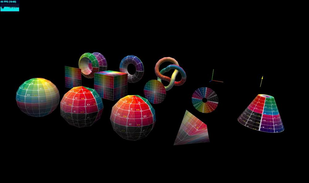
To see Three.js prebuilt geometry in action, run the sample located in the Three.js project at examples/webgl_geometries.html, depicted in Figure 4-1. Each mesh object contains a different geometry type, with a reference texture map displaying how texture coordinates are generated for each. The texture comes courtesy of PixelCG Tips and Tricks, a great computer graphics how-to site. The scene is lit with a directional light to show the shading for each object.
Paths, Shapes, and Extrusions
The Three.js Path, Shape, and ExtrudeGeometry classes provide many flexible ways to generate geometry—for example, to create
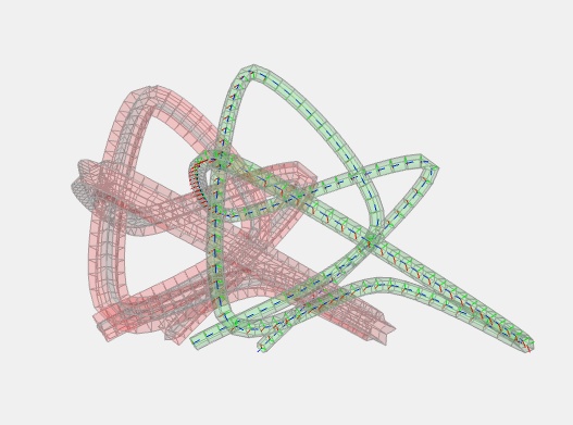
extruded objects from curves. Figure 4-2 shows an extrusion
generated from a spline-based curve. To see it in action, run the sample
under the Three.js project at examples/webgl_geometry_extrude_shapes.html.
Another sample, examples/webgl_geometry_extrude_splines.html,
allows you to interactively select from a variety of spline generation
algorithms and even follow the spline curve using an animated camera. Combining splines
with extrusions is a great technique for generating organic-looking
shapes. Spline curves are described in detail in Chapter 5.
The Shape classes can also be
used to create flat 2D shapes or 3D extrusions of those shapes. Let’s
say you have an existing library of 2D polygon data (for example,
geopolitical boundaries or vector clip art). You can fairly easily
import that data into Three.js by using the Path class, which includes path-generation
methods, such as moveTo() and
lineTo(), that should be familiar to
people with 2D drawing experience. (Essentially this is a 2D drawing API
embedded in a 3D drawing library.) Why do this? Well, once you have your
2D shape, you can use it to create a flat mesh that lives in 3D space:
it can be transformed like any other 3D object (translated, rotated, scaled); it can be
painted with materials and lit and shaded like anything else in your
scene. You can also extrude it to create a true 3D shape based on the 2D
outline.
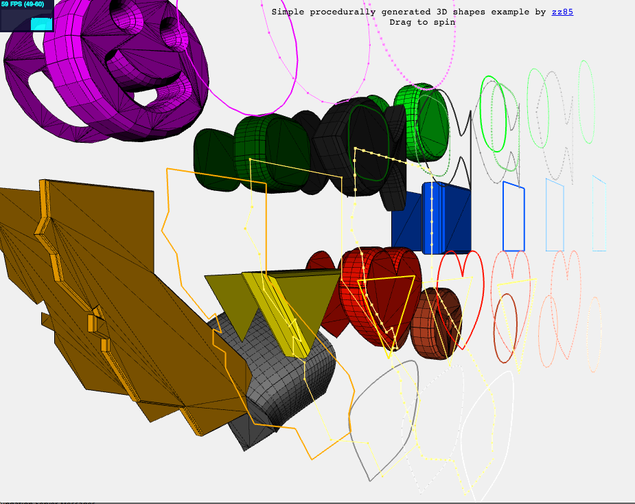
The demo in the file examples/webgl_geometry_shapes.html, depicted in Figure 4-3, shows an excellent example of this capability. We can see the outline of the state of California, some simple polygons, and whimsical hearts and smiley faces rendered in several forms, including flat 2D meshes, extruded and beveled 3D meshes, and lines—all derived from path-based data.
The Geometry Base Class
The Three.js prebuilt geometry types are derived from the base class THREE.Geometry (src/core/Geometry.js). You can also use this
class by itself to programmatically generate your own geometry. Have a
look at the source code for the prebuilt types, located in the Three.js
project under the folder src/extras/geometries/, to get a feel for how
those classes implement geometry generation. To illustrate, let’s take a
quick look at one of the simpler objects, THREE.CircleGeometry. Example 4-1 lists the code for this
object, in its entirety, which fits on a single page.
/**
 * @author hughes
 */

THREE.CircleGeometry = function ( radius, segments, thetaStart, thetaLength ) {

    THREE.Geometry.call( this );

    radius = radius || 50;

    thetaStart = thetaStart !== undefined ? thetaStart : 0;
    thetaLength = thetaLength !== undefined ? thetaLength : Math.PI * 2;
    segments = segments !== undefined ? Math.max( 3, segments ) : 8;

    var i, uvs = [],
    center = new THREE.Vector3(), centerUV = new THREE.Vector2( 0.5, 0.5 );

    this.vertices.push(center);
    uvs.push( centerUV );

    for ( i = 0; i <= segments; i ++ ) {

        var vertex = new THREE.Vector3();
        var segment = thetaStart + i / segments * thetaLength;

        vertex.x = radius * Math.cos( segment );
        vertex.y = radius * Math.sin( segment );

        this.vertices.push( vertex );
        uvs.push( new THREE.Vector2( ( vertex.x / radius + 1 ) / 2,
            ( vertex.y / radius + 1 ) / 2 ) );

    }

    var n = new THREE.Vector3( 0, 0, 1 );

    for ( i = 1; i <= segments; i ++ ) {

        var v1 = i;
        var v2 = i + 1 ;
        var v3 = 0;

        this.faces.push( new THREE.Face3( v1, v2, v3, [ n, n, n ] ) );
        this.faceVertexUvs[ 0 ].push( [ uvs[ i ], uvs[ i + 1 ], centerUV ] );

    }

    this.computeCentroids();
    this.computeFaceNormals();

    this.boundingSphere = new THREE.Sphere( new THREE.Vector3(), radius );

};

THREE.CircleGeometry.prototype = Object.create( THREE.Geometry.prototype );
The constructor for THREE.CircleGeometry generates a flat,
circular shape in the XY plane; that is, all
z values are set to zero. At the heart of this
algorithm is the code to generate the vertex data for such a shape,
located within the first for
loop:
vertex.x = radius * Math.cos( segment );
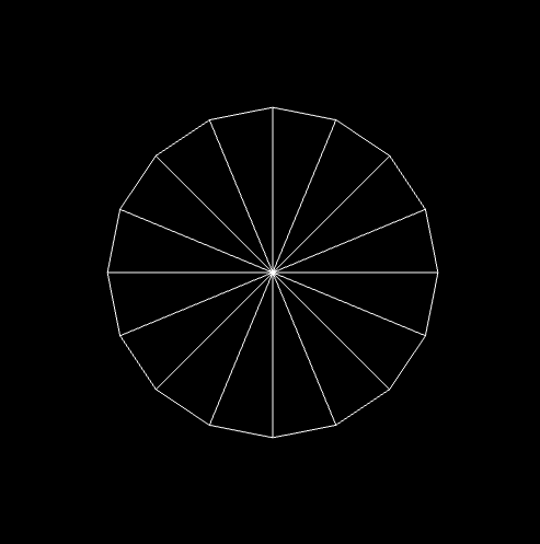
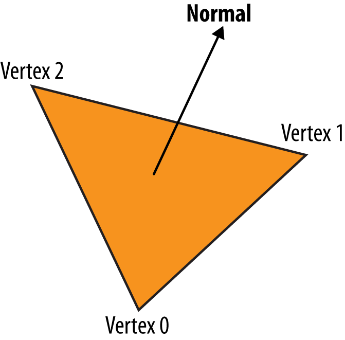
vertex.y = radius * Math.sin( segment );In reality, the 3D circle is just a fan of triangles radiating from the center. By supplying enough triangles, we can create the illusion of a smooth edge around the perimeter. See Figure 4-4.
The first loop just took care of calculating the
x and y vertex positions for
the circumference of the circle. Now we have to create a
face (polygonal shape) to represent each triangle,
constructed of three vertices: the center, located at the origin; and two
additional vertices positioned at the perimeter. The second for loop does that by creating and populating
the array this.faces. Each face
contains the indices for three vertices from the array this.vertices, indexed by indices v1, v2, and
v3. Note that v3 is always equal to zero; that vertex
corresponds to the origin. (You may recall the WebGL details from Chapter 2, where gl.drawElements() is used to render triangles using an indexed array. The same
thing is going on here, being handled under the covers by
Three.js.)
We glossed over one detail in each of the loops: texture
coordinate generation. WebGL doesn’t know how to map the pixels of a
texture map onto the triangles it draws without us telling it how. In a
similar way to how we created the vertex values, the two for loops generate texture coordinates, also known as UV coordinates, and store them in
this.faceVertexUVs.
Recall that texture coordinates are floating-point pairs defined
for each vertex, with values typically ranging from 0 to 1. These values
represent x, y offsets into
the bitmap image data; the shader will use these values to get pixel
information from the bitmap. We calculate the texture coordinate for the
first two vertices in each triangle in a similar manner to the vertex
data, by using the cosine of the angle for the x
value and the sin for the y value, but generating
values in the range [0..1] by
dividing the vertex values by the radius of the circle. The texture
coordinate for the third vertex of each triangle, corresponding to the
vertex at the origin, is simply the 2D center of the image (0.5,
0.5).
Note
Why UV? The letters U and V are used to denote the horizontal and vertical axes of a 2D texture map because X, Y, and Z are already used to denote the 3D axes of the object’s coordinate system. For a complete exploration of the topic of UV coordinates and UV mapping, you can refer to the Wikipedia entry.
Once the vertex and UV data has been generated, Three.js has all
it needs to render the geometry. The final lines of code in the THREE.Circle constructor are essentially doing
bookkeeping, using helper functions supplied by the base geometry class.
computeCentroids() determines
the geometric center of the object by looping through all
its vertices, averaging positions.
computeFaceNormals() is very
important, because the object’s normal vectors, or
normals, determine how it is shaded. For a flat circle, the normals
for each face are perpendicular to the geometry. computeFaceNormals() easily determines this by
computing a vector perpendicular to the plane defined by the three
vector positions making up each triangle of the circle. The face normal
for a flat-shaded triangle is depicted in Figure 4-5.
Finally, the constructor initializes a bounding volume for the object, in this case a sphere, which is useful for picking, culling, and performing a number of optimizations.
BufferGeometry for Optimized Mesh Rendering
Three.js recently introduced an optimized version of geometry
called THREE.BufferGeometry.
THREE.BufferGeometry stores its data as typed arrays,
avoiding the extra overhead of dealing with arrays of JavaScript
numbers. This class is also handy for static geometry, such as scene
backgrounds and props, where you know the vertex values never change and
the objects are never animated to move around the scene. If you know
that to be true, you can create a THREE.BufferGeometry object, and Three.js will
do a series of optimizations that render these objects really fast.
Importing Meshes from Modeling Packages
So far we have looked at creating geometry in code. But many, if not most, applications will not be creating geometry programmatically; instead, they will be loading 3D models created by professional modeling packages such as 3ds Max, Maya, and Blender.
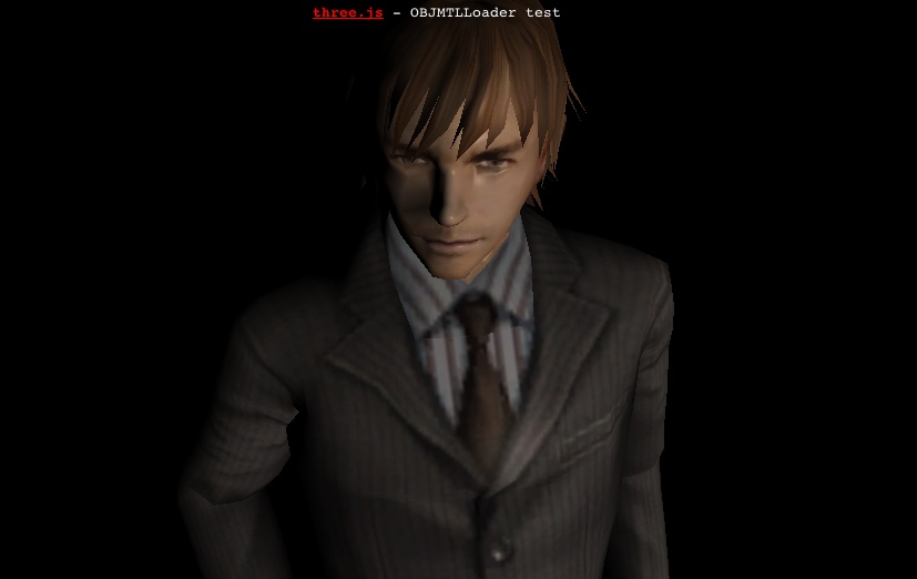
Three.js has several utilities to convert and/or load model files. Let’s look at one example of loading a mesh, including its geometry and materials. Run the file examples/webgl_loader_obj_mtl.html under the Three.js project. You will see the model shown in Figure 4-6.
The male figure depicted here was imported via the Wavefront OBJ format (.OBJ file extension). This is a popular text-based format exported by many modeling packages. OBJ files are simple and limited, containing only geometry data: vertices, normals, and texture coordinates. Wavefront developed a companion file format for materials, MTL, which can be used to associate materials with the objects in the OBJ file.
The source code for the Three.js OBJ format loader (with
materials) is located in examples/js/loaders/OBJMTLLoader.js. Take a
look at how it works and you will see that, as with the prebuilt
geometry and shape classes, Three.js file loaders create THREE.Geometry objects to represent the
geometry. The MTL parser translates text options in the MTL file into
materials Three.js understands. The two are then combined into a
THREE.Mesh object suitable for adding to the scene.
Three.js has sample loaders for many different file formats. While most formats include support for defining objects with geometry and materials, many go beyond that, representing entire scenes, cameras, lights, and animations. We will cover those formats (and the tools to author them) in detail in Chapter 8, which is devoted to the content creation pipeline.
Note
Most of the file loading code that comes with Three.js is not in the core library, but rather included with the examples. You will have to include them separately in your projects. Unless otherwise indicated, these file loader utilities are covered under the same licensing as the library and you can feel free to use them in your work.
The Scene Graph and Transform Hierarchy
WebGL has no built-in notion of 3D scene structure; it is simply an API for drawing to the canvas. It is up to the application to provide scene structure. Three.js defines a model for structuring scenes based on the well-established concept of a scene graph. A scene graph is a set of 3D objects stored in a hierarchical parent/child relationship, with the base of the scene graph often referred to as the root. The application renders the scene graph by rendering the root and then, recursively, its descendants.
Using Scene Graphs to Manage Scene Complexity
Scene graphs are particularly useful for representing complex objects in a hierarchy. Think of a robot, a vehicle, or a solar system: each of these has several individual parts— limbs, wheels, satellites—with their own behaviors. The scene graph allows these objects to be treated as either individual parts or as entire groups, as needed. This is not only for organizational convenience: it can also provide a very important capability known as transform hierarchy, where an object’s descendants inherit its 3D transformation information (translation, rotation, scale). For example, say you are animating a car driving along a path. The car body moves along the path, but the wheels also rotate independently. By making the wheels children of the car body, your code can dynamically move the car along the path, and the wheels will move through 3D space with it; there is no need to separately animate the movement of the wheels, only their rotation.
Note
The use of the word graph in the Three.js scene graph is somewhat loose technically. In 3D rendering, the scene graph usually refers to a directed acyclic graph (DAG), which is a mathematical term that denotes a set of nodes in a parent/child relationship in which any object can have multiple parents. In the Three.js scene graph, objects can have only one parent. While it is technically correct to call the Three.js hierarchy a graph, it would more precisely be called a tree. For more information on graphs in mathematics, refer to the Wikipedia entry.
Scene Graphs in Three.js
The foundation object of the Three.js scene graph is THREE.Object3D (see src/core/Object3D.js under the Three.js
project sources). It is used both as the base class for visual types
such as meshes, lines, and particle systems, as well as on its own to
group other objects into a scene graph hierarchy.
Each Object3D carries its own
transform information, represented in the properties position
(translation), rotation, and scale. By setting these, you can move, rotate,
and scale the object. If the object has descendants (children and their
children), those will inherit these transformations. If those
descendants’ transform properties have been changed, those changes will
combine with those of the ancestors all the way down the hierarchy.
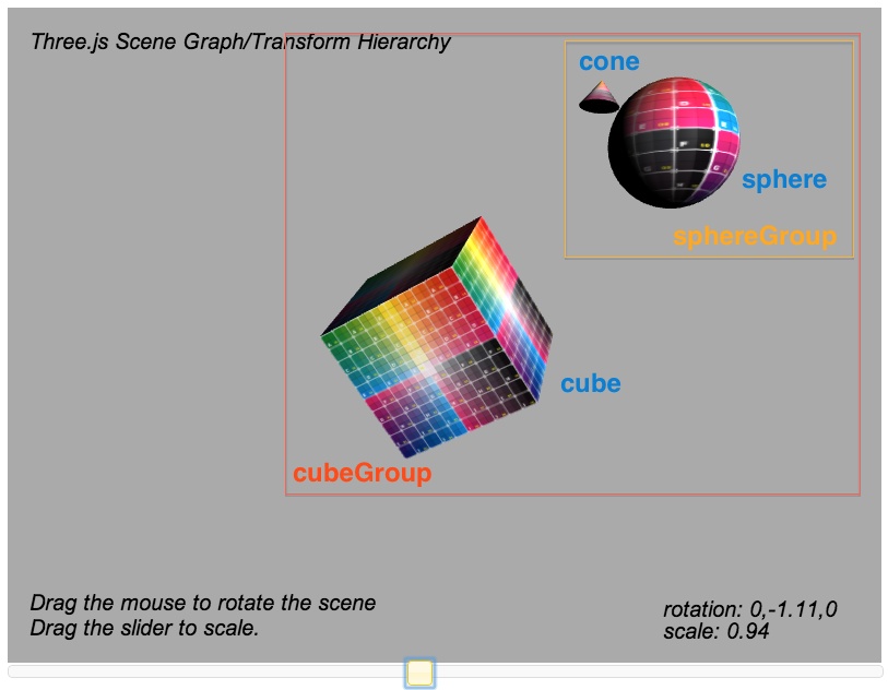
Let’s look at an example. The page depicted in Figure 4-7 shows a very
simple transform hierarchy. cube is a
direct descendant of cubeGroup;
sphereGroup is also a direct
descendant of cubeGroup (and
therefore a sibling of cube); and
sphere and cone are descendants of sphereGroup.
Run this sample by loading the example file Chapter 4/threejsscene.html. You will see the cube, sphere, and cone each rotating in place. You can interact with this scene: clicking and dragging the mouse in the content area rotates the entire scene; dragging the slider below the content area scales the scene.
Example 4-2 shows the
relevant code for creating and manipulating the scene graph with
transform hierarchy. The really important lines are highlighted in bold.
First, to construct the scene: we create a new Object3D, cubeGroup, that will act as the root of the
scene graph. We then add the cube mesh directly to it, as well as
another Object3D: sphereGroup. The sphere and cone are added to
sphereGroup. We also move the cone a
bit up and away from the sphere by setting its position property.
Now for the animations: we see in function animate() that when sphereGroup rotates, the sphere rotates, and
the cone seems to orbit around the sphere and traverse through space.
Note that we did not write any code to individually rotate the sphere
mesh or move the cone through space every animation frame; because those
objects inherit their transform information from sphereGroup, those operations are taken care
of for us automatically. In a similar way, interacting with the scene to
rotate and scale it is trivially simple: we just set the rotation and scale properties, respectively, of cubeGroup, and these changes are propagated to
its descendants automatically by Three.js.
function animate() {

        var now = Date.now();
        var deltat = now - currentTime;
        currentTime = now;
        var fract = deltat / duration;
        var angle = Math.PI * 2 * fract;

        // Rotate the cube about its Y axis
        cube.rotation.y += angle;

        // Rotate the sphere group about its Y axis
        sphereGroup.rotation.y -= angle / 2;

        // Rotate the cone about its X axis (tumble forward)
        cone.rotation.x += angle;
    }

        function createScene(canvas) {

        // Create the Three.js renderer and attach it to our canvas
        renderer = new THREE.WebGLRenderer( { canvas: canvas, antialias: true } );

        // Set the viewport size
        renderer.setSize(canvas.width, canvas.height);

        // Create a new Three.js scene
        scene = new THREE.Scene();

        // Add a camera so we can view the scene
        camera = new THREE.PerspectiveCamera( 45, canvas.width / canvas.height,
            1, 4000 );
        camera.position.z = 10;
        scene.add(camera);

        // Create a group to hold all the objects
        cubeGroup = new THREE.Object3D;

        // Add a directional light to show off the objects
        var light = new THREE.DirectionalLight( 0xffffff, 1.5);
        // Position the light out from the scene, pointing at the origin
        light.position.set(.5, .2, 1);
        cubeGroup.add(light);

        // Create a textured phong material for the cube
        // First, create the texture map
        var mapUrl = "../images/ash_uvgrid01.jpg";
        var map = THREE.ImageUtils.loadTexture(mapUrl);
        var material = new THREE.MeshPhongMaterial({ map: map });

        // Create the cube geometry
        var geometry = new THREE.CubeGeometry(2, 2, 2);

        // And put the geometry and material together into a mesh
        cube = new THREE.Mesh(geometry, material);

        // Tilt the mesh toward the viewer
        cube.rotation.x = Math.PI / 5;
        cube.rotation.y = Math.PI / 5;

        // Add the cube mesh to our group
        cubeGroup.add( cube );

        // Create a group for the sphere
        sphereGroup = new THREE.Object3D;
        cubeGroup.add(sphereGroup);

        // Move the sphere group up and back from the cube
        sphereGroup.position.set(0, 3, −4);

        // Create the sphere geometry
        geometry = new THREE.SphereGeometry(1, 20, 20);

        // And put the geometry and material together into a mesh
        sphere = new THREE.Mesh(geometry, material);

        // Add the sphere mesh to our group
        sphereGroup.add( sphere );

        // Create the cone geometry
        geometry = new THREE.CylinderGeometry(0, .333, .444, 20, 5);

        // And put the geometry and material together into a mesh
        cone = new THREE.Mesh(geometry, material);

        // Move the cone up and out from the sphere
        cone.position.set(1, 1, -.667);

        // Add the cone mesh to our group
        sphereGroup.add( cone );

        // Now add the group to our scene
        scene.add( cubeGroup );
    }

    function rotateScene(deltax)
    {
        cubeGroup.rotation.y += deltax / 100;
        $("#rotation").html("rotation: 0," + cubeGroup.rotation.y.toFixed(2) + ",0");
    }

    function scaleScene(scale)
    {
        cubeGroup.scale.set(scale, scale, scale);
        $("#scale").html("scale: " + scale);
    }
Representing Translation, Rotation, and Scale
In Three.js, transformations are done via 3D matrix math, so not
surprisingly, the components of Object3D’s transform are 3D vectors: position, rotation, and scale. position should be fairly self-explanatory:
its x, y, and
z components define a vector offset from the
object’s origin. scale is also
straightforward: x, y, and
z values are used to
multiply the transformation matrix’s scale by that amount in
each of the three dimensions.
The components of rotation
require a little more explanation: each of x,
y, and z defines a rotation
around that axis; for example, a value of (0,
Math.PI / 2, 0) is equivalent to a 90-degree rotation around
the object’s y-axis. (Note that degrees are specified in radians, where
2 * pi radians is equivalent to 360 degrees). This type of rotation—a
combination of angles about the x, y, and z-axes—is known as a Euler angle. I assume Mr.doob chose Eulers as the base representation because
they are so intuitive and easy to work with; however, they are not
without their mathematical problems in practice. For that reason,
Three.js also allows you to use quaternions, another form
of specifying angles that is free from Euler issues, but requires more
programming work. Quaternions are accurate, but not intuitive to work
with.
Under the hood, Three.js is using the transform properties of each
Object3D to construct a matrix. Objects that have
multiple ancestors have their matrices multiplied by those of their
ancestors in recursive fashion; that is, Three.js traverses all the way
down to each leaf in its scene graph tree to calculate the transform
matrix for each object every time the scene is rendered. This can get
expensive for deep and complex scene graphs. Three.js defines a matrixAutoUpdate property for Object3D, which can be set to false to
avoid this performance overhead. However, this feature has the potential
to cause subtle bugs (“Why isn’t my animation updating?”), so it should
be used with great care.
Materials
The visual shapes we see in WebGL applications have surface properties such as color, shading, and textures (bitmaps). Creating those properties using the low-level WebGL API entails writing GLSL shader code, which requires advanced programming skills, even for the simplest visual effects. Lucky for us, Three.js comes with ready-to-go GLSL code, packaged into objects called materials.
Standard Mesh Materials
Recall that WebGL requires the developer to supply a programmable shader in order to draw each object. You may have noticed the absence of GLSL shader source code thus far in this chapter. That is for a very good reason: Three.js does the shader coding for us, with a library of predefined GLSL code suitable for a variety of uses out of the box.
Traditional scene graph libraries and popular modeling packages typically represent shaders via the concept of materials. A material is an object that defines the surface properties of a 3D mesh, point, or line primitive, including color, transparency, and shininess. Materials may or may not also include texture maps—that is, bitmaps wrapped onto the surface of the object. Material properties combine with the vertex data of the mesh, lighting information in the scene, and potentially the camera position and other global properties to determine the final rendered appearance of each object.
Three.js supports common material types in the prebuilt classes MeshBasicMaterial, MeshPhongMaterial, and MeshLambertMaterial. (The Mesh prefix denotes that these material types
should be used in combination with the mesh object, as opposed to lines
or particles; there are additional material types suitable for use with
other object types. See the Three.js objects that live in the project
source under src/materials for a
complete and up-to-date set.) These material types implement,
respectively, three well-known material techniques:
- Unlit (also known as prelit)
With this material type, only the textures, colors, and transparency values are used to render the surface of the object. There is no contribution from lights in the scene. This is a great material type to use for flat-looking renderings and/or for drawing simple geometric objects with no shading. It is also valuable if the lighting for objects has been precomputed into the textures prior to runtime (for example, by a 3D modeling tool with a light “baking” utility), and thus does not have to be computed by the renderer.
- Phong shading
This material type implements a simple, fairly realistic-looking shading model with high performance. It has become the go-to material type for achieving a classic shaded look quickly and easily and is still used in many games and applications. Phong-shaded objects will show brightly lit areas (specular reflections) where light hits directly, will light well along any edges that mostly face the light source, and will darkly shade areas where the edge of the object faces away from the light source.
- Lambertian reflectance
In Lambert shading, the apparent brightness of the surface to an observer is the same regardless of the observer’s angle of view. This works really well for clouds, which broadly diffuse the light that strikes them, or satellites such as moons that have high albedo (reflect light brightly off the surface).
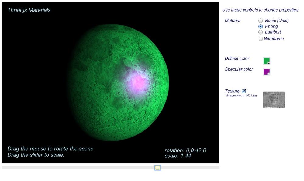
To get a feel for the Three.js material types, open the lab in the book example code, located in the file Chapter 4/threejsmaterials.html. The page, shown in Figure 4-8, displays a brightly lit sphere with a texture map of the moon. The moon is a good object to use here to illustrate differences between the various material types. Use the radio buttons to switch between Phong and Lambert, for example, to see how much more appropriate Lambert shading looks than Phong for this object. Now use the Basic (unlit) shader to see how the sphere appears rendered with just the texture and no lighting applied.
Try changing the diffuse and specular colors to see those effects. The material’s diffuse color specifies how much the object reflects lighting sources that cast rays in a direction—that is, directional, point, and spotlights (see the discussion on lighting later in this chapter). The specular color combines with scene lights to create reflected highlights from any of the object’s vertices facing toward light sources. (Note that specular highlights will be visible only when the Phong material is used; the other material types do not support specular color.) Also, try turning the texture map off with the checkbox so that you can see the effects of the material on simple sphere geometry. Finally, check the wireframe box to see how various changes affect the wireframe rendering.
Adding Realism with Multiple Textures
The previous example shows how a texture map can be used to define the surface look for an object. Most Three.js material types actually support applying multiple textures to the object to create more realistic effects. The idea behind using multiple textures in a single material, or multitexturing, is to provide a computationally inexpensive way to add realism—versus using more polygons or rendering the object with multiple render passes. Here are a few examples to illustrate the more common multitexturing techniques supported in Three.js.
Bump maps
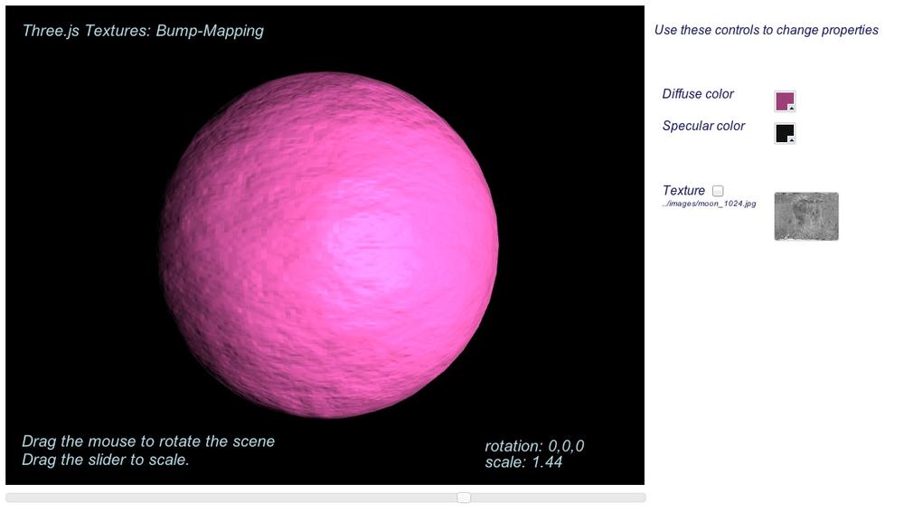
A bump map is a bitmap used to displace the surface normal vectors of a mesh to, as the name suggests, create an apparently bumpy surface. The pixel values of the bitmap are treated as heights rather than color values. For example, a pixel value of zero can mean no displacement from the surface, and nonzero values can mean positive displacement away from the surface. Typically, single-channel black and white bitmaps are used for efficiency, though full RGB bitmaps can be used to provide greater detail, since they can store much larger values. The reason that bitmaps are used instead of 3D vectors is that they are more compact and provide a fast way to calculate normal displacement within the shader code. To see bump maps in action, open the example Chapter 4/threejsbumpmap.html, depicted in Figure 4-9. Turn the main moon texture on and off, and play with the diffuse and specular color values to see different results. You will probably notice that, while the effect can be really cool, it can also yield unpleasant artifacts. Still, bump maps provide a cheap way to add realistic detail.
Bump maps are trivially easy to use in Three.js. Simply
provide a valid texture in the bumpMap property of the parameter object
you pass to the THREE.MeshPhongMaterial
constructor:
        material= new THREE.MeshPhongMaterial({map: map,
          bumpMap: bumpMap });
Normal maps
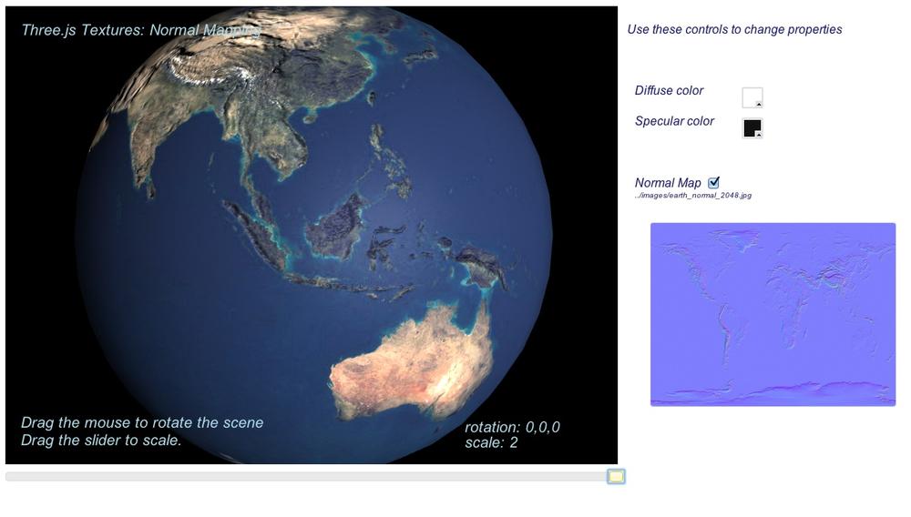
Normal maps provide a way to get even more surface detail than bump maps, still without using extra polygons. Normal maps tend to be larger and require more processing power than bump maps, but the extra detail can be worth it. Normal maps work by encoding actual vertex normal vector values into bitmaps as RGB data, typically at a much higher resolution than the associated mesh vertex data. The shader incorporates the normal information into its lighting calculations (along with current camera and light source values) to provide apparent surface detail. Open the example Chapter 4/threejsnormalmap.html file to see the effect of a normal map. The normal map is depicted in the swatch on the bottom right (see Figure 4-10). Note the outlines of the Earth’s elevation features. Now toggle the normal map on and off to see how much detail it is providing; it is quite astonishing how much detail a bitmap can add to a simple object like a sphere.
Normal maps are also easy to use in Three.js. Simply provide a
valid texture in the normalMap property of the parameter object
you pass to the THREE.MeshPhongMaterial
constructor:
        Material = new THREE.MeshPhongMaterial({ map: map,
          normalMap: normalMap });
Environment maps
Environment maps provide another way to use extra textures to increase realism. Instead of adding surface detail through apparent changes to the geometry, as with bump maps and normal maps, environment maps simulate reflection of objects in the surrounding environment.
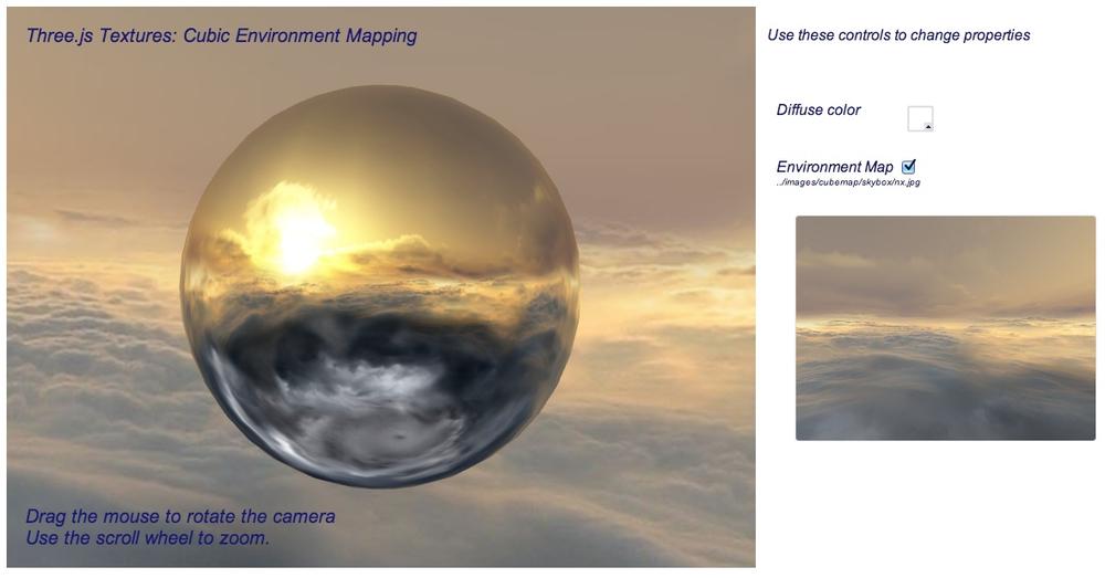
Open Chapter 4/threejsenvmap.html to see a demonstration of environment mapping. Drag the mouse in the content area to rotate the scene, or use the mouse wheel to zoom in and out. Notice how the image on the surface of the sphere appears to reflect the sky background surrounding it (see Figure 4-11). In fact, it does no such thing; it is simply rendering pixels from the same texture that is mapped onto the inside of the cube used for the scene’s background. The trick here is that the texture being used on the sphere’s material is a cube texture: a texture map made up of six individual bitmaps stitched together to form a contiguous image on the inside of a cube. This particular cube texture has been created to form a sky background panorama. Have a look at the individual files that make up this skybox in the folder images/cubemap/skybox/ to see how it is constructed. This type of environment mapping is called cubic environment mapping, because it employs cube textures.
Using cube textures in Three.js is slightly more involved than
using bump or normal maps. First, we need to create a cube texture
instead of a regular texture. We do this with the Three.js utility ImageUtils.loadTextureCube(), passing it
URLs for the six individual image files. Then, we set this as the
value of the envMap
parameter of the MeshPhongMaterial when calling the
constructor. We also specify a reflectivity value defining how much of
the cube texture will be “reflected” on the material when the object
is rendered. In this case, we supply a value slightly higher than
the default of 1, to make sure the environment map really stands
out.
        var path = "../images/cubemap/skybox/";

        var urls = [ path + "px.jpg", path + "nx.jpg",
                     path + "py.jpg", path + "ny.jpg",
                     path + "pz.jpg", path + "nz.jpg" ];

        envMap = THREE.ImageUtils.loadTextureCube( urls );
        materials["phong-envmapped"] = new THREE.MeshBasicMaterial(
           { color: 0xffffff,
             envMap : envMap,
             reflectivity:1.3} );
There is more to be done. In order for this to be a realistic
effect, the reflected bitmap needs to correspond to the surrounding
environment. To make that happen, we create a skybox—that is, a large
background cube textured from the inside with the same bitmap images
representing a panoramic sky. This in itself could be a lot of work
but, thankfully, Three.js has a built-in helper that does it for us.
In addition to its prebuilt standard materials Basic, Phong, and
Lambert, Three.js includes a library of utility shaders, contained
in the global THREE.ShaderLib. We simply create a mesh
with cube geometry, and as the material we use the Three.js “cube”
shader defined in the library. It takes care of rendering the inside
of the cube using the same texture as we used for the environment
map.
        // Create the skybox
        var shader = THREE.ShaderLib[ "cube" ];
        shader.uniforms[ "tCube" ].value = envMap;

        var material = new THREE.ShaderMaterial( {

            fragmentShader: shader.fragmentShader,
            vertexShader: shader.vertexShader,
            uniforms: shader.uniforms,
            side: THREE.BackSide

        } ),

        mesh = new THREE.Mesh(new THREE.CubeGeometry( 500, 500, 500 ), material);
        scene.add( mesh );
Lights
Lights illuminate objects in the 3D scene. Three.js defines several built-in light classes that correspond to those typically found in modeling tools and other scene graph libraries. The most commonly used light types are directional lights, point lights, spotlights, and ambient lights.
- Directional lights
Represent a light source that casts parallel rays in a particular direction. They have no position, only a direction, color, and intensity. (In fact, in Three.js, directional lights do have a position, but it is used only to calculate the light’s direction based on the position and a second vector, the target position. This is a clumsy and counterintuitive syntax that I hope Mr.doob someday fixes.)
- Point lights
Have a position but no direction; they cast their light in all directions from their position, over a given distance.
- Spotlights
Have a position and a direction. They also have parameters defining the size (angle) of the spotlight’s inner and outer cones, and a distance over which they illuminate.
- Ambient lights
Have no position or direction. They illuminate a scene equally throughout.
All Three.js light types support the common properties intensity, which defines the light’s strength,
and color, an RGB value.
Lights do not do their job on their own; their values combine with
certain properties of materials to define an object’s ultimate surface
appearance. MeshPhongMaterial and
MeshLambertMaterial define the
following properties:
colorAlso known as the diffuse color, this specifies how much the object reflects lighting sources that cast rays in a direction (i.e., directional, point, and spotlights).
ambientThe amount of ambient scene lighting reflected by the object.
emissiveThis material property defines the color an object emits on its own, irrespective of light sources in the scene.
MeshPhongMaterial also supports a specular
color, which combines with scene lights to create reflected highlights
from the object’s vertices that are facing toward light sources.
Recall that MeshBasicMaterial
ignores lights completely.
Figure 4-12 depicts a lighting experiment built with the basic Three.js light types. Open the file Chapter 4/threejslights.html to run it. The scene contains four lights, one of each type, and displays a simple black-and-white textured ground plane and three plain white geometry objects to illustrate the effects of the various lights. The color picker controls on the page allow you to interactively change the color of each light. Set a light’s color to black, and it will turn the light off completely. Drag the mouse within the content area to rotate around the scene and see the effects of the lights on various parts of the model.

The following code listing shows the light setup code. The white
directional light positioned in front of the scene lights bright white
areas on the front of the geometry objects. The blue point light
illuminates from behind the model; note the blue areas on the floor to the
back of the object. The green spotlight casts its cone toward the floor
near the front of the scene, as defined by spotLight.target.position. Finally, the ambient
light provides a small amount of illumination to all objects in the scene
equally. Play with the controls and inspect the model from all sides to
see the individual and combined effects of the lights.
         // Create and add all the lights
        directionalLight.position.set(.5, 0, 3);
        root.add(directionalLight);

        pointLight = new THREE.PointLight (0x0000ff, 1, 20);
        pointLight.position.set(−5, 2, −10);
        root.add(pointLight);

        spotLight = new THREE.SpotLight (0x00ff00);
        spotLight.position.set(2, 2, 5);
        spotLight.target.position.set(2, 0, 4);
        root.add(spotLight);

        ambientLight = new THREE.AmbientLight ( 0x888888 );
        root.add(ambientLight);
Note
At this juncture, here is a friendly reminder about what is going on. As with nearly everything else in WebGL, lights are an artificially created construct. WebGL knows only about buffers and shaders; developers need to synthesize lighting effects by writing shader code. Three.js offers an astounding set of material and lighting capabilities…all the more incredible when you realize that it was written in JavaScript. Of course, none of this would be possible if WebGL didn’t give us access to the GPU to create these amazing effects in the first place.
Shadows
For years, designers have used shadows to add an extra visual cue that enhances realism. Typically these are faked, prerendered affairs, and moving the light source or any of the shadowed objects destroys the illusion. However, Three.js allows us to render shadows in real time based the current positions of the lights and objects.
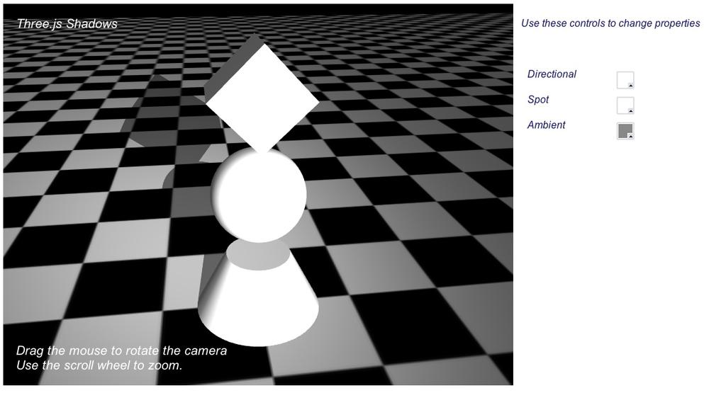
The example in the file Chapter 4/threejsshadows.html demonstrates how to add real-time shadows to a scene. Refer to Figure 4-13: the geometry casts shadows onto the ground plane based on a spotlight positioned above the ground and in front of the scene. Note how the shadow follows the shape of the rotating cube. Also, as the floor rotates, the shadow does not move along with it. If the shadows were faked with prerendering, the shadow would stay “glued” to the floor and it would not rotate along with the cube. Play with the light controls, in particular the spotlight, to see how the shadow changes dynamically.
Three.js supports shadows using a technique called shadow mapping. With shadow mapping, the renderer maintains an additional texture map, to which it renders the shadowed areas and combines with the final image in its fragment shaders. So, enabling shadows in Three.js requires a few steps:
Let’s take a look at how this is done in code. Example 4-3 shows the code added to createScene() to render shadows, highlighted in
boldface.
    var SHADOW_MAP_WIDTH = 2048, SHADOW_MAP_HEIGHT = 2048;

    function createScene(canvas) {

        // Create the Three.js renderer and attach it to our canvas
        renderer = new THREE.WebGLRenderer( { canvas: canvas, antialias: true } );

        // Set the viewport size
        renderer.setSize(canvas.width, canvas.height);

        // Turn on shadows
        renderer.shadowMapEnabled = true;
        renderer.shadowMapType = THREE.PCFSoftShadowMap;

        // Create a new Three.js scene
        scene = new THREE.Scene();

        // Add a camera so we can view the scene
        camera = new THREE.PerspectiveCamera( 45, canvas.width / canvas.height,
            1, 4000 );
        camera.position.set(-2, 6, 12);
        scene.add(camera);

        // Create a group to hold all the objects
        root = new THREE.Object3D;

        // Add a directional light to show off the object
        directionalLight = new THREE.DirectionalLight( 0xffffff, 1);

        // Create and add all the lights
        directionalLight.position.set(.5, 0, 3);
        root.add(directionalLight);

        spotLight = new THREE.SpotLight (0xffffff);
        spotLight.position.set(2, 8, 15);
        spotLight.target.position.set(−2, 0, −2);
        root.add(spotLight);

        spotLight.castShadow = true;

        spotLight.shadowCameraNear = 1;
        spotLight.shadowCameraFar = 200;
        spotLight.shadowCameraFov = 45;

        spotLight.shadowDarkness = 0.5;

        spotLight.shadowMapWidth = SHADOW_MAP_WIDTH;
        spotLight.shadowMapHeight = SHADOW_MAP_HEIGHT;

        ambientLight = new THREE.AmbientLight ( 0x888888 );
        root.add(ambientLight);

        // Create a group to hold the spheres
        group = new THREE.Object3D;
        root.add(group);

        // Create a texture map
        var map = THREE.ImageUtils.loadTexture(mapUrl);
        map.wrapS = map.wrapT = THREE.RepeatWrapping;
        map.repeat.set(8, 8);

        var color = 0xffffff;
        var ambient = 0x888888;
        // Put in a ground plane to show off the lighting
        geometry = new THREE.PlaneGeometry(200, 200, 50, 50);
        var mesh = new THREE.Mesh(geometry, new THREE.MeshPhongMaterial({color:color,
            ambient:ambient, map:map, side:THREE.DoubleSide}));
        mesh.rotation.x = -Math.PI / 2;
        mesh.position.y = −4.02;

        // Add the mesh to our group
        group.add( mesh );
        mesh.castShadow = false;
        mesh.receiveShadow = true;

        // Create the cube geometry
        geometry = new THREE.CubeGeometry(2, 2, 2);

        // And put the geometry and material together into a mesh
        mesh = new THREE.Mesh(geometry, new THREE.MeshPhongMaterial({color:color,
            ambient:ambient}));
        mesh.position.y = 3;
        mesh.castShadow = true;
        mesh.receiveShadow = false;

        // Add the mesh to our group
        group.add( mesh );

        // Save this one away so we can rotate it
        cube = mesh;

        // Create the sphere geometry
        geometry = new THREE.SphereGeometry(Math.sqrt(2), 50, 50);

        // And put the geometry and material together into a mesh
        mesh = new THREE.Mesh(geometry, new THREE.MeshPhongMaterial({color:color,
            ambient:ambient}));
        mesh.position.y = 0;
        mesh.castShadow = true;
        mesh.receiveShadow = false;

        // Add the mesh to our group
        group.add( mesh );

        // Create the cylinder geometry
        geometry = new THREE.CylinderGeometry(1, 2, 2, 50, 10);

        // And put the geometry and material together into a mesh
        mesh = new THREE.Mesh(geometry, new THREE.MeshPhongMaterial({color:color,
            ambient:ambient}));
        mesh.position.y = −3;

        mesh.castShadow = true;
        mesh.receiveShadow = false;

        // Add the  mesh to our group
        group.add( mesh );

        // Now add the group to our scene
        scene.add( root );
    }
First, we enable shadows in the renderer by setting renderer.shadowMapEnabled to true and setting its shadowMapType property to THREE.PCFSoftShadowMap. Three.js supports three
different types of shadow mapping algorithms: basic, PCF (for “percentage
close filtering”), and PCF soft shadows. Each algorithm provides
increasing realism, at the expense of higher complexity and slower
performance. Try experimenting with this sample by changing the shadowMapType to THREE.BasicShadowMap and THREE.PCFShadowMap and have a look at the
results; shadow quality degrades noticeably with the lower-quality
settings. But you may need to go that route for performance if your scenes
are complex.
Next, we need to enable shadow casting for the spotlight. We set its
castShadow property to true. We also set several parameters required by
Three.js. Three.js renders shadows by casting a ray from the position of
the light toward its target object. Essentially, it treats the spotlight
as another “camera” for rendering the scene from the position. So we must
set camera-like parameters, including near and far clipping planes and
field of view. The near and far values are very much dependent on the size
of the scene and objects, so we chose fairly small values for both. The
field of view was determined empirically. We also provide a darkness value
for the shadow; the Three.js default of 0.5 is suitable for this
application. Then, we set properties that determine the size of the
Three.js-generated shadow map. The shadow map is an additional bitmap
created by Three.js into which it will render the shadow dark areas and
ultimately blend with the final rendered
image of each object. Our values for SHADOW_MAP_WIDTH and SHADOW_MAP_HEIGHT are 2,048, which is much higher
than the Three.js default of 512. This produces very smooth shadows; lower
values will yield more jagged results. Experiment with this value in the
example to see how lower-resolution shadow maps affect shadow
quality.
Finally, we must tell Three.js which objects cast and receive
shadows. By default, Three.js meshes do not cast or receive shadows, so we
must set this explicitly. In this example, we want the solid geometries to
cast shadows onto the floor, and the floor to receive the shadows. So, for
the floor we set mesh.castShadow to
false and mesh.receiveShadow to true; for the cube, sphere, and cone we set
mesh.castShadow to true and mesh.receiveShadow to false.
As a finishing touch, we would like the intensity of the shadow to
correspond to the brightness of the spotlight casting it. However,
Three.js shadow mapping does not automatically take into account the
brightness of the light sources when rendering shadows. Rather, it uses the light’s
shadowDarkness property. So, as the
color of the spotlight is updated via the user interface, we need to
update shadowDarkness ourselves. The
following fragment shows the code for the helper function setShadowDarkness(), which calculates a new
value for the shadow darkness based on the average brightness of the light
color’s red, green, and blue components. As you change the spotlight’s
color in the demo to a darker value, you will see the shadow fade
away.
    function setShadowDarkness(light, r, g, b)
    {
        r /= 255;
        g /= 255;
        b /= 255;
        var avg = (r + g + b) / 3;

        light.shadowDarkness = avg * 0.5;
    }
Note
Real-time shadows are a fantastic enhancement to the WebGL visual experience, and Three.js makes them fairly easy to work with. However, they come at a cost. First, the shadow map, which is just another texture map, requires additional graphics memory; for a 2,048 × 2,048 map, that amounts to an additional 4 MB. See if you can get away with smaller shadow map sizes and still get the desired visual effect. Also, depending on the graphics hardware being used, rendering off-screen to the shadow map can introduce extra processing overhead that slows down frame rate considerably. So, you must take care when using this feature. Be ready to profile and, potentially, fall back to another solution that doesn’t require real-time shadows.
Shaders
Three.js provides a powerful set of materials out of the box, implemented via predefined GLSL shaders included with the library. These shaders were developed to support commonly used shading styles, such as unlit, Phong, and Lambert. But there are many other possibilities. In the general case, materials can implement a limitless variety of effects, can use many and variegate properties, and can get arbitrarily complex. For example, a shader simulating grass blowing in the wind might have parameters that determine the height and thickness of the grass and the wind speed and direction.
As computer graphics evolved, and production values rose over the last two decades—originally for film special effects and later for real-time video games—shading started looking more like a general-purpose programming problem than an art production exercise. Instead of trying to predict every potential combination of material properties and code them into a runtime engine, the industry banded together to create programmable pipeline technology, known as programmable shaders, or simply shaders. Shaders allow developers to write code that implements complex effects on a per-vertex and per-pixel basis in a C-style language compiled for execution on the GPU. Using programmable shaders, developers can create highly realistic visuals with high performance, freed from the constraints of predefined material and lighting models.
The ShaderMaterial Class: Roll Your Own
GL Shading Language (GLSL) is the shading language developed for use with Open GL and OpenGL ES (the basis for the WebGL API). GLSL
source code is compiled and executed for use with WebGL via methods of
the WebGL context object. Three.js hides GLSL under the covers for us,
allowing us to completely bypass shader programming if we so choose. For
many applications, the prebuilt material types suffice. But if our
application needs a visual effect that is not supplied out of the box,
Three.js also allows us to write custom GLSL shaders using the class
THREE.ShaderMaterial.
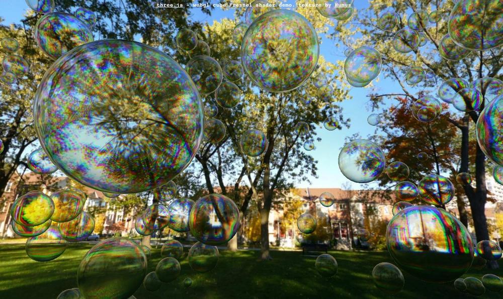
Figure 4-14 shows
an example of ShaderMaterial in
action. This example, which can be found under the Three.js project tree
at examples/webgl_materials_shaders_fresnel.html,
demonstrates a Fresnel shader. Fresnel shading is used to simulate the reflection and
refraction of light through transparent media such as water and
glass.
Note
Fresnel shaders (pronounced “fre-nel”) are named after the Fresnel Effect, first documented by the French physicist Augustin-Jean Fresnel (1788–1827). Fresnel advanced the wave theory of light through a study of how light was transmitted and propagated by different objects. For more information, consult the online 3D rendering glossary.
The setup code in this example creates a ShaderMaterial as follows: it clones the
uniform (parameter) values of the FresnelShader template object—each instance of
a shader needs its own copy of these—and passes the GLSL source code for
the vertex and fragment shaders. Once these are set up, Three.js will
automatically handle compiling and linking the shaders, and binding
JavaScript properties to the uniform values.
                var shader = THREE.FresnelShader;
                var uniforms = THREE.UniformsUtils.clone( shader.uniforms );

                uniforms[ "tCube" ].value = textureCube;

                var parameters = {
                   fragmentShader: shader.fragmentShader,
                   vertexShader: shader.vertexShader,
                   uniforms: uniforms };

                var material = new THREE.ShaderMaterial( parameters );
The GLSL code for the Fresnel shader is shown in Example 4-4. The source can also be found under the Three.js project tree in the file examples/js/shaders/FresnelShader.js. This shader code was written by frequent Three.js contributor Branislav Ulicny, better known by his “nom de code,” AlteredQualia. Let’s walk through the listing to see how it is done.
/**
 * @author alteredq / http://alteredqualia.com/
 * Based on Nvidia Cg tutorial
 */

THREE.FresnelShader = {

    uniforms: {

        "mRefractionRatio": { type: "f", value: 1.02 },
        "mFresnelBias": { type: "f", value: 0.1 },
        "mFresnelPower": { type: "f", value: 2.0 },
        "mFresnelScale": { type: "f", value: 1.0 },
        "tCube": { type: "t", value: null }

    },
The uniforms property of
THREE.ShaderMaterial specifies
the values Three.js will pass to WebGL when the shader is
used. Recall that the shader program is executed for each vertex and
each pixel (fragment). Shader uniforms are
values that, as the name implies, do not change from
vertex to vertex; they are essentially global variables whose value is
the same for all vertices and pixels. The Fresnel shader in this example
defines uniforms controlling the amount of reflection and refraction
(e.g., mRefractionRatio and mFresnelScale). It also defines a uniform for
the cube texture used as the scene background. In a similar fashion to
the cubic environment-mapping sample we saw in a previous section, this
shader simulates reflection by rendering the pixels from the cube map.
However, with this shader, we will see not only pixels reflected from
the cube map, but refracted ones as well.
Using GLSL Shader Code with Three.js
Now it’s time to set up the vertex and fragment shaders. First, the vertex shader:
    vertexShader: [

        "uniform float mRefractionRatio;",
        "uniform float mFresnelBias;",
        "uniform float mFresnelScale;",
        "uniform float mFresnelPower;",

        "varying vec3 vReflect;",
        "varying vec3 vRefract[3];",
        "varying float vReflectionFactor;",

        "void main() {",

            "vec4 mvPosition = modelViewMatrix * vec4( position, 1.0 );",
            "vec4 worldPosition = modelMatrix * vec4( position, 1.0 );",

            "vec3 worldNormal = normalize( mat3( modelMatrix[0].xyz, ",
            "    modelMatrix[1].xyz, modelMatrix[2].xyz ) * normal );",

            "vec3 I = worldPosition.xyz - cameraPosition;",

            "vReflect = reflect( I, worldNormal );",
            "vRefract[0] = refract( normalize( I ), worldNormal, ",
            "    mRefractionRatio );",
            "vRefract[1] = refract( normalize( I ), worldNormal, ",
            "    mRefractionRatio * 0.99 );",
            "vRefract[2] = refract( normalize( I ), worldNormal, ",
            "    mRefractionRatio * 0.98 );",
            "vReflectionFactor = mFresnelBias + mFresnelScale * ",
            "    pow( 1.0 + dot( normalize( I ), worldNormal ), ",
            "    mFresnelPower );",

            "gl_Position = projectionMatrix * mvPosition;",

        "}"

    ].join("\n"),
The vertex shader program is the workhorse for this particular
material. It uses the camera position and the position of each vertex of
the model—in this example, the sphere geometry used for the bubble
shape—to calculate a direction vector, which is then used to compute
reflection and refraction coefficients for each vertex. Note the
varying declarations in the vertex
and fragment shader programs. Unlike uniform variables, varying
variables are computed for each vertex and are passed along from the
vertex to the fragment shader. In this way, the vertex shader can output
values in addition to the built-in gl_Position that is its primary job to
compute. For the Fresnel shader, the varying outputs are the reflection
and refraction coefficients.
The Fresnel vertex shader also makes use of several varying and
uniform variables that we do not see here because they are predefined by
Three.js, and passed to the GLSL compiler automatically: modelMatrix, modelViewMatrix, projectionMatrix, and cameraPosition. These values do not need
to be—in fact, should not be—explicitly declared by the shader
programmer.
modelMatrix(uniform)The world transformation matrix for the model (mesh). As discussed in the section The Scene Graph and Transform Hierarchy, this matrix is computed by Three.js every frame to determine the world space position of an object. Within the shader, it is used to calculate the world space position of each vertex.
modelViewMatrix(uniform)The transformation representing each object’s position in camera space—that is, in coordinates relative to the position and orientation of the camera. This is particularly handy for computing camera-relative values (e.g., to determine reflection and refraction, which is exactly what is being done in this shader).
projectionMatrix(uniform)Used to calculate the familiar 3D-to-2D projection from camera space into screen space.
cameraPosition(uniform)The world space position of the camera maintained by Three.js and passed in automatically.
position(varying)normal(varying)
The vertex shader also makes use of built-in GLSL functions, reflect() and refract(), to compute reflection and
refraction vectors based on the camera direction, normal, and refraction
ratio. (These functions were built into the GLSL language because they
are so generally useful for lighting computations like the Fresnel
equations.)
Finally, note the use of Array.join() to
set up the vertex shader. This illustrates yet another useful technique
for putting together the long text strings that implement shaders in the
GLSL language. Rather than escaping newlines at the end of each line of
code and using string concatenation, we use join() to insert newlines between each line of
code.
From here, the fragment shader’s job is straightforward. It uses the
reflection and refraction values computed by the vertex shader to index
into the cube texture passed in the uniform variable tCube. This variable is of type samplerCube, a GLSL type designed to handle
cube textures. We blend these two colors using the GLSL function
mix(), to produce the final pixel
output by storing it in the built-in gl_FragColor.
    fragmentShader: [

        "uniform samplerCube tCube;",

        "varying vec3 vReflect;",
        "varying vec3 vRefract[3];",
        "varying float vReflectionFactor;",

        "void main() {",

            "vec4 reflectedColor = textureCube( tCube, ",
            "    vec3( -vReflect.x, vReflect.yz ) );",
            "vec4 refractedColor = vec4( 1.0 );",

            "refractedColor.r = textureCube( tCube, ",
            "    vec3( -vRefract[0].x, vRefract[0].yz ) ).r;",
            "refractedColor.g = textureCube( tCube, ",
            "    vec3( -vRefract[1].x, vRefract[1].yz ) ).g;",
            "refractedColor.b = textureCube( tCube, ",
            "    vec3( -vRefract[2].x, vRefract[2].yz ) ).b;",

            "gl_FragColor = mix( refractedColor, ",
            "    reflectedColor, clamp( vReflectionFactor, ",
            "    0.0, 1.0 ) );",

        "}"

    ].join("\n")

};
Creating a custom shader may seem like a lot of work, but the final result is worth it, as it produces a very convincing simulation of real-world optics. And the extra machinery Three.js puts in place for us—keeping world matrices up to date per object, tracking the camera, predeclaring dozens of GLSL variables, compiling and linking the shader code—saves us literally days of development and debugging effort and makes the thought of developing our own custom shaders not only conceivable, but inviting. With this framework in place, you should feel free to experiment writing your own shaders. I suggest starting with the Fresnel and other shaders that come with the Three.js samples. There are many different kinds of effects and a lot to learn in there.
Rendering
This chapter has climbed a Three.js ladder of sorts, an ascent of increasing realism that began with the drawing of simple geometric shapes, up through materials, textures, lights, and shadows, and eventually to writing our own shaders in GLSL. We have climbed high, creating more realistic graphics at each step, but we are not quite at the top. Believe it or not, there is one more rung: rendering.
The ultimate output of manipulating the Three.js 3D scene graph is a 2D image rendered onto a browser Canvas element. Whether we achieve this by using WebGL, using the 2D Canvas drawing API, or fiddling with CSS to move elements around on the page is almost irrelevant; the end goal is painting pixels. We choose to use WebGL because it can get the job done fast. Using the other technologies we might—might—be able to achieve many of these visual effects, but not an acceptable frame rate. So we often choose WebGL.
This being said, even with WebGL we have several choices about exactly how to have it render images. For example, the API allows us to use Z-buffered rendering—where the hardware uses additional memory to paint only those pixels frontmost in the scene—or not. It’s our choice. If we don’t use Z-buffering, our application will have to sort objects itself, potentially down to the triangle level. That sounds like a big hassle, but depending on the use case, we may want to do exactly that. This is but one such choice we can make regarding rendering.
Three.js was designed to make it easy to do basic graphics. The
built-in WebGL renderer is ready to go with game-quality graphics
without causing too much developer grief. As we have seen in the examples
thus far, it’s as easy as 1) creating the renderer, 2) setting the
viewport dimensions, and 3) calling render(). But the library also allows us to do
much more, providing the ability to control the WebGL rendering process at
a fine-grained level. When this capability is combined with advanced
rendering techniques such as post-processing, multipass rendering, and
deferred rendering, we can create some truly realistic effects.
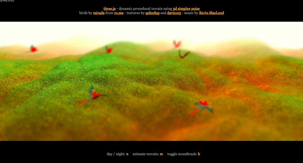
Post-Processing and Multipass Rendering
Sometimes, one render isn’t enough. It often takes several renderings of a scene with different parameters to create a high-quality, realistic-looking image. These separate renderings, or passes, are ultimately combined together to produce the final image in a process known as multipass rendering. Many multipass rendering approaches involve using post-processing, or improving an image’s quality via image-processing techniques.
Post-processing and multipass rendering have become increasingly popular in real-time 3D rendering, so the authors of Three.js have taken great pains to support it. Figure 4-15 shows a subtle yet dramatic example of Three.js post-processing written by AlteredQualia. Load the file examples/webgl_terrain_dynamic.html. Birds flock majestically over an otherworldly landscape in the foggy dawn light. As if the simplex noise-based, procedurally generated terrain weren’t impressive enough, this piece also features multiple render passes, including bloom shading to emphasize the bright sunlight diffusing through the morning fog, and a Gaussian filter to softly blur the scene, further enhancing the scene’s serene qualities.
Three.js post-processing relies on the following features:
Support for multiple render targets via the
THREE.WebGLRenderTargetobject. With multiple render targets, a scene can be rendered more than once to off-screen bitmaps and then combined later in a final image. (Source file: src/renderers/WebGLRenderTarget.js.)A multipass rendering loop implemented in class
THREE.EffectComposer. This object contains one or more render pass objects that it will call in succession to render the scene. Each pass has access to the entire scene as well as the image data produced by the previous pass, allowing it to further refine the image.
THREE.EffectComposer, and the
sample multipass techniques that use it, are located in the Three.js project folder examples,
under examples/js/postprocessing/
and examples/js/shaders/. A scan of
these folders will unearth a treasure trove of post-processing special
effects.
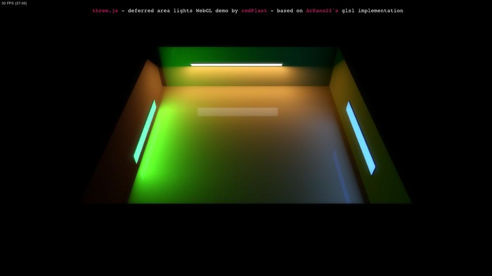
Deferred Rendering
We have one more rendering approach to explore: deferred rendering. As the name implies, this approach delays rendering to the WebGL canvas until a final image is computed from multiple sources. Unlike multipass rendering, which successively renders a scene and refines the image before finally copying it to the WebGL canvas, deferred rendering employs multiple buffers (actually just texture maps) into which the data required for the shading computations is gathered in an initial pass. In a subsequent pass, the pixel values are calculated with the values gathered from the first pass. This approach can be memory- and computationally expensive, but it can produce highly realistic effects, especially with respect to lighting and shadows. See Figure 4-16 for an example.
Chapter Summary
This chapter covered broad ground, touching on most of the graphics drawing and rendering capabilities present in Three.js. We saw how to use the prebuilt geometry classes to easily create 3D solids, meshes, and parameterized and extruded shapes. We discussed the Three.js scene graph and transform hierarchy for constructing complex scenes. We got hands-on experience with materials, textures, and lighting. Finally, we explored how programmable shaders and advanced rendering techniques such as post-processing and deferred rendering can increase visual realism. The graphics features in Three.js represent a massive arsenal, packaged up in an accessible and easy-to-use library. These facilities, combined with the raw power of WebGL, allow us to create nearly any 3D visuals we can imagine.
Get Programming 3D Applications with HTML5 and WebGL now with the O’Reilly learning platform.
O’Reilly members experience books, live events, courses curated by job role, and more from O’Reilly and nearly 200 top publishers.

