5.9. SIMULINK Block Diagrams
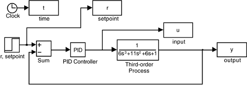
SIMULINK is a natural environment for simulating closed-loop systems. It is recommended that you read Module 2, Introduction to SIMULINK, and reproduce the simulation results shown in Example 5.3. Generate the block diagram shown in Figure 5-18 and run the simulations for various controller proportional gains.
Figure 5-18. SIMULINK diagram for Example 5.3.
Recall that the closed-loop characteristic equation for Example 5.3 is
![]()
For kc + 10, the MATLAB roots command can be used to find that the process is on the verge ...
Get Process Control: Modeling, Design, and Simulation now with the O’Reilly learning platform.
O’Reilly members experience books, live events, courses curated by job role, and more from O’Reilly and nearly 200 top publishers.

