M15.1. Motivating Example
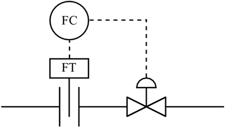
Consider the control schematic diagram for the flow control loop shown in Figure M15-1. In practice, this loop contains a number of components, as detailed in Figure M15-2.
Figure M15-1. Schematic instrumentation diagram for a flow controller.

Figure M15-2. More detailed instrumentation diagram for a flow controller.

We can see that this loop consists of the following components.
Flowmeter— often an orifice plate meter. The volumetric flow rate is proportional to the square root of the pressure drop across the orifice plate ...
Get Process Control: Modeling, Design, and Simulation now with the O’Reilly learning platform.
O’Reilly members experience books, live events, courses curated by job role, and more from O’Reilly and nearly 200 top publishers.

