6.2 Rectifier Model
6.2.1 Space Vector Model
The AFE rectifier is modeled as shown in Figure 6.3. The rectifier is a fully controlled bridge with power transistors, connected to the three-phase supply voltages vs using the filter inductances Ls and resistances Rs.
Figure 6.3 AFE rectifier
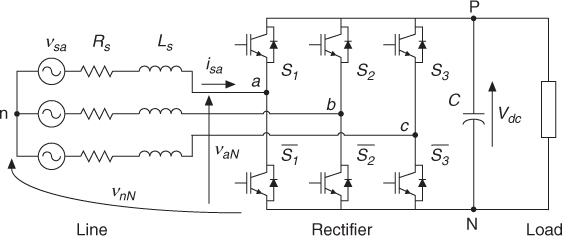
Considering the circuit shown in Figure 6.3, the equations for each phase can be written as
6.2 ![]()
Then, considering the space vector definition for the grid voltage
where a = ej2π/3, and by substituting (6.1)–(6.3) into (6.4), the vector equation for the grid current dynamics can be obtained as
Note that the last term of this equation is equal to zero
6.6 ![]()
The input current dynamics equation (6.5) can be simplified by considering the following definitions for the grid current vector and ...
Get Predictive Control of Power Converters and Electrical Drives now with the O’Reilly learning platform.
O’Reilly members experience books, live events, courses curated by job role, and more from O’Reilly and nearly 200 top publishers.

