1.2 Types of Power Converters
There are many types of power converters and drive systems, and every application requires different specifications that define the most appropriate topology and control scheme to be used. A general scheme for a drive system and a simple classification of the different types of power converters are presented next.
1.2.1 Generic Drive System
A block diagram and a picture of a real drive system are shown in Figure 1.2. The main components of the system are the line-side transformer, the rectifier, the DC link, the inverter, the electrical machine, and the control unit. Depending on the system requirements, the rectifier can be a diode rectifier or an active front-end rectifier. The DC link is composed of capacitors or inductors, depending on the topology of the inverter and rectifier, whose purpose is to store energy and decouple the operation of the inverter and rectifier. The inverter modulates the DC link voltage (or current) and generates a voltage whose fundamental component can be adjusted in amplitude, frequency, and phase, in order to control the torque and speed of the machine. The control unit samples voltage and current measurements of the most important variables and generates the gate drive signals for the power semiconductor devices.
Figure 1.2 General motor drive system (AFE = Active Front-End)
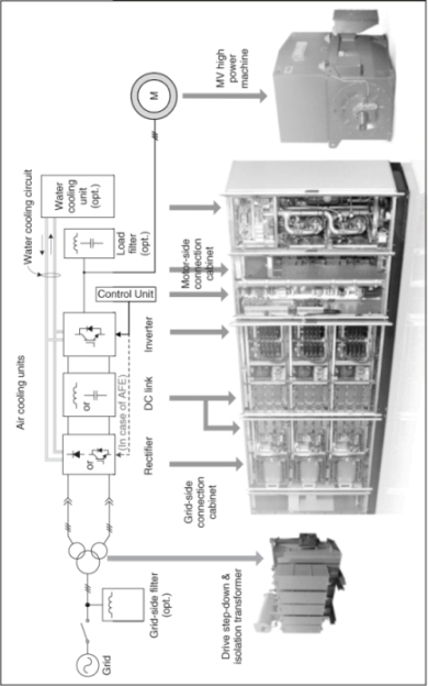
As can be observed in Figure 1.2, the drive ...
Get Predictive Control of Power Converters and Electrical Drives now with the O’Reilly learning platform.
O’Reilly members experience books, live events, courses curated by job role, and more from O’Reilly and nearly 200 top publishers.

