A.1 Predictive Current Control of a Three-Phase Inverter
One of the most common converter topologies found in industry is the three-phase voltage source inverter. Since several other converter topologies have operation principles that are similar to those of the three-phase voltage source inverter, the simulation of the predictive control algorithm in this converter can serve as a starting point for further developments.
Figure A.1 shows the MATLAB/Simulink model used for simulation of the predictive current control of the voltage source inverter described in Chapter 4. The simulation diagram is composed of five major elements: the references, coordinate transformations, predictive control algorithm, inverter model, and load model.
Figure A.1 Simulink model for simulation of predictive current control of a voltage source inverter
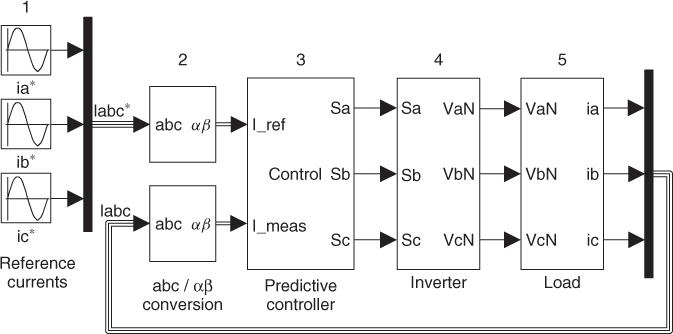
The three-phase current references are generated by sine wave sources (block 1), which are configured with the desired peak amplitude, frequency, and phase angle. The predictive control algorithm can be directly implemented for three-phase currents. However, in order to reduce the number of predictions, the control can be performed in two-phase complex coordinates (αβ coordinates). Since both the reference current and the load current measurements are three-phase variables, the coordinate transformation needs to be applied to each signal. In some applications ...
Get Predictive Control of Power Converters and Electrical Drives now with the O’Reilly learning platform.
O’Reilly members experience books, live events, courses curated by job role, and more from O’Reilly and nearly 200 top publishers.

