RTP is a protocol framework that is deliberately not complete. This document specifies those functions expected to be common across all the applications for which RTP would be appropriate. Unlike conventional protocols ⦠RTP is intended to be tailored through modifications and/or additions to the headers as needed.
VoIP endpoint registration, setup, number dialing, media sessions and features are all governed by the VoIP signaling protocol. Probably the most common signaling protocols in use today are the Session Initialization Protocol (SIP), H.323 from the International Telecommunications UnionâTelecom (ITU-T), and the Skinny Client Control Protocol (Skinny) from Cisco. These three protocols could not be more different from each other. But, despite these differences, they share the need to transport voice data from one phone to another, and they all use the same methodâthe Real-Time Transport Protocol, or RTP. While RTP is used on almost every standardized Voice over IP deployment, its malleable nature allows it to be expanded or modified to suit future media streams and codecs.
This chapter will describe the operation of RTP and provide several examples of packets captured on an operating VoIP network. Mixed in with the RTP packets, we will also see another protocolâthe real-time control protocol (RTCP), which provides feedback regarding the quality or performance of the RTP stream. One challenge in writing a chapter like this is that vendors do not implement these protocols in the same way, so the chapter will review captures taken from different deployments to illustrate the ideas. Thus, the packets shown in this chapter will come from a collection of Cisco, Avaya, and Polycom topologies.
RTP and RTCP were originally defined in RFC 1889. This RFC was made obsolete by RFC 3550. This chapter will use the latter as the primary resource. The companion document to RFC 3550 is RFC 3551 (3551 obsoletes RFC 1890), which defines an RTP profile for audio and video conferencing. Much of the information required to fully understand the operation of RTP (and its malleability) is also contained in RFC 3551, so this will be an integral part of the discussion.
If you have read the previous chapters, you know that there are many components required to support a VoIP deployment, such as a signaling protocol, and infrastructure, such as the trivial file transfer protocol (TFTP) server and dynamic host configuration, or DHCP. These conversations occur before the RTP stream starts. The signaling protocol only returns for termination of the call. So, the signaling protocol (H.323, SIP, Skinny) and the transport protocol (RTP) handle different aspects of the communication. Per RFC 3550, RTP does the following:
Provides end-to-end delivery services for data with real-time characteristics, such as interactive audio and video.
In this context, delivery service means that RTP is the container for the voice or video data or both. The data is the result of the codec operation. So, voice and/or video is sampled per the codec and then placed inside an RTP packet. An example of this is shown in Figure 4-1.
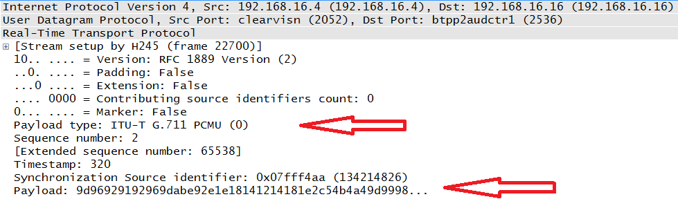
This packet indicates that the payload was created via the G.711 codec, as indicated by the top arrow. G.711 is an audio codec used to generate voice frames (the process is described in chapter 5) that constitute the payload; this is indicted by the bottom arrow. The receiver of audio data has to know exactly what codec was used to create the packet and how to put the stream back together. While there are several fields in an RTP packet, the protocol has two main focal points: payload identification and sequencing.
At layer 4 of our networking models, RTP is encapsulated in a UDP header. UDP provides very little in the way of priority handling or sequencing. This is common for real-time data simply because a lost or significantly delayed packets might create problems if the application at the destination has to wait for them. But this is not true of the TCP-based signaling protocol. The signaling protocol handles the other operations, such as registration and call setup. However, once data starts to flow, it is placed in an RTP wrapper. Thus, RTP is often built into an application. One other feature of RTP is that it is expandable and flexible. For example, payload types can be added to the RFC, and security additions such as secure RTP need not rewrite the entire header.
Note
While RFC 3550 obsoletes RFC 1889, it does not mean that there have been major changes to the structure or operation. The major aspects of RTP and RTCP actually change very little. From RFC 3550:
Most of the text in this memorandum is identical to RFC 1889 which it obsoletes. There are no changes in the packet formats on the wire, only changes to the rules and algorithms governing how the protocol is used.
So, when reviewing RTP packets, we might expect headers defined by the most recent RFC. However, most transmissions use RFC 1889.
The idea of a profile must now be introduced. While RFC 3550 describes the general structure and operation of both RTP and RTCP, there are some items that can be modified through the use of a profile. A type of transmission may desire an additional function outside of the fixed header defined in the RFC. Both the marker and payload fields (defined later in this chapter) can be slightly modified to suit these needs. In addition, a collection of fixed fields can be added immediately before the payload field. This is described by an extension to the header.
Section 5.3 of RFC 3550 provides more information about the profile modifications and the header extensions. RFC 3551 contains the profile for audio and video in a conferencing application. Importantly, this RFC contains the RTP payload-field values used by the common audio and video codecs.
RTP is used to convey the real-time data. Typically this will be voice and/or video. So, the signaling protocol (H.323, Skinny, or SIP) will be used to handle the messages used to establish calls or connections. Part of this is the negotiation of the method used to encode the data. Chapters 3, 6, and 7 show how SIP, H.323, and Skinny handle this. Once a media session has been established, the RTP packets begin to flow between the endpoints in both directions. The packets from each source are tied together via an identification number.
Since the performance of real-time data is critical with latency, packet loss, and jitter resulting in poor perceived call quality, RTP has a control protocol used to measure some of these values. Thus, RTCP packets are also sent along with the RTP stream although they are much fewer in number. The point of RTCP is to keep track of the RTP stream and provide this information to the endpoints. Specifically, RTCP counts the number of packets and bytes sent. It also measures the transmission times for the RTP packets. When RTP and RTCP are together, the UDP port used by RTCP is supposed to be the next highest odd numbered port.
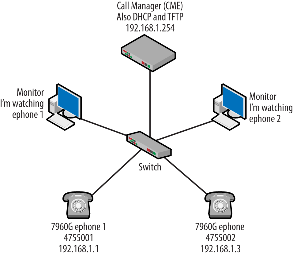
To help with the explanation of these ideas, we will use the topology shown in Figure 4-2.
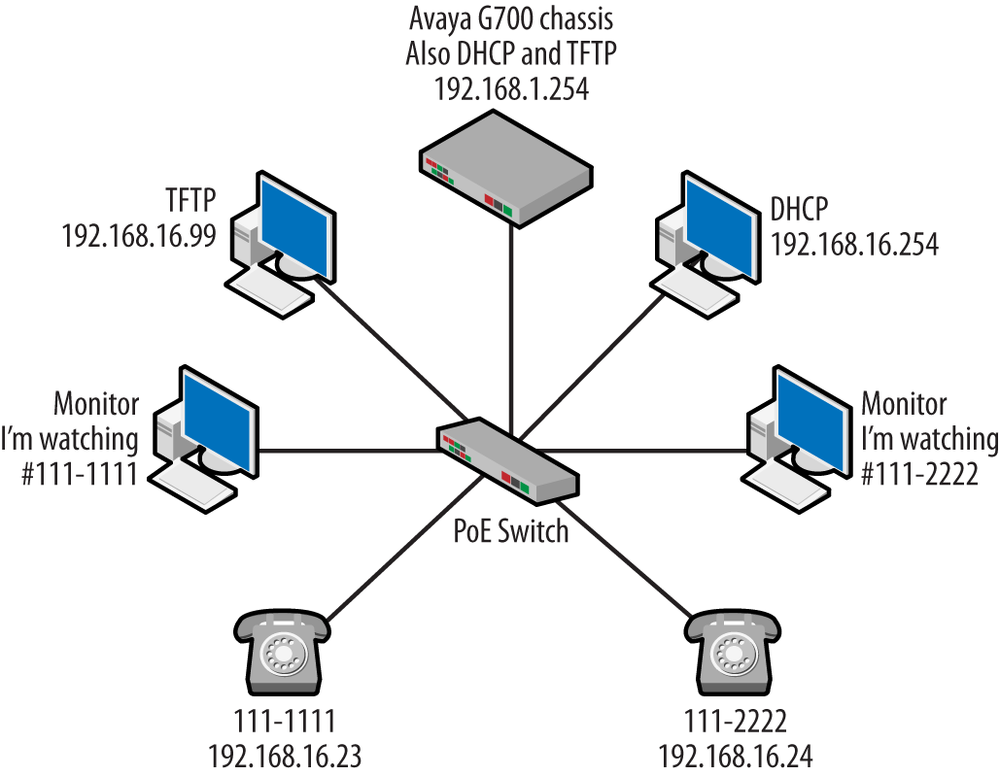
An Avaya G700 chassis will be our call server. This topology happens to use the H.323 suite of protocols. Like the other topologies discussion in this book, a dynamic host configuration protocol (DHCP) server and trivial file transfer protocol (TFTP) servers will also be present. The two VoIP phones have been given the numbers 111-1111 (192.168.16.23) and 111-2222 (192.168.16.24), and there are management stations observing traffic flowing to and from the two phones via monitor sessions running on the switch. The following sections will describe the structure of the RTP and RTCP protocols using this topology.
The nice thing about RTP is that it is a fairly straightforward protocol with a small set of header fields. In this section, we will discuss what are called the fixed-header fields. The text version of the header is taken from RFC 1889 and can be seen in Figure 4-3.
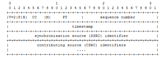
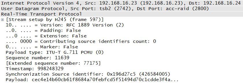
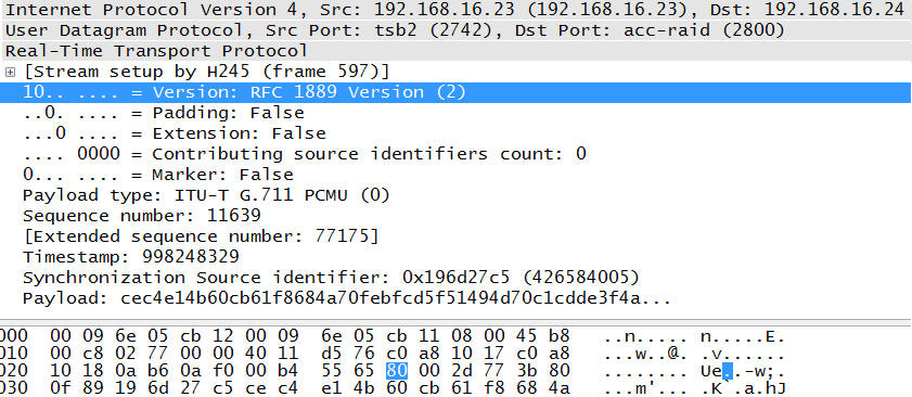
The next section will provide details, but first letâs compare the RFC header in Figure 4-3 with an actual RTP packet as shown in Figure 4-4. The first couple of fields are very small and include information regarding the content of the packet. But some of the most important fields will be PT or Payload Type (G.711), the sequence number (11639), timestamp (998248329), and the SSRC, or synchronization source identifier. As the fields are defined, the following section will refer to both diagrams for clarification.
The first octet of the RTP header is a collection of small fields. The binary value of 1000 0000 (80 in hexadecimal) can easily be broken down into these subfields. The highlighted line of Figure 4-5 begins the first octet, and this is reflected in the hexadecimal at the bottom. This particular packet is only a portion of the one weâve been using in this section. It has been edited for space but not for content. The three periods a the very end of the decoded portion (3f4aâ¦) simply indicate that there is more payload than would fit on the screen.
Subfield Descriptions
- Version (V)
This is a 2-bit field indicating the protocol variant. Possible values include:
- 0
Pre-RTP; indicates the vat audio tool
- 1
First draft version of RTP
- 2
Current version of RTP
An interesting note is that both RFC 1889 and 3550 use the phrase âversion defined by this specificationâ when the value in this field two. The fact that both RFCs use the same value in this field is another indication that there is not much difference between them. From Figure 4-5, we can see that the value is 10 in binary and that Wireshark considers this compliant with RFC 1889.
- Padding (P)
This single-bit field tells us whether or not the packet contains octets that are not part of the audio or video payload making up the stream. A zero indicates that this padding is not included. Should padding be part of the packet, the last octet of the padding provides the number of padded octets. Some implementations use fixed block sizes that may not be filled by the samples and so require padding.
- Extension (X)
This is another single-bit field indicating the status of the current packet. As mentioned earlier, RTP is an extendable protocol; this allows functions that were defined after the current RFCs to be integrated smoothly into the protocol. Should an extension be required, the header will be enlarged once to contain the function defined by the extension, which happens in a fixed manner described by RFC 3550.
- Contributing Source Identifiers Count (CC)
RTP has the ability to carry several samples, and these may be from different sources, as would happen in conference calling with multiple participants. To handle this case, RTP must provide a method to separate the samples and the source for each so that the streams can be reconstructed at the receiving end. If the value of this 4-bit field is set to zero (0000 in binary), then there is a single source associated with this packet. If the value is nonzero, it contains the number of other sources present.
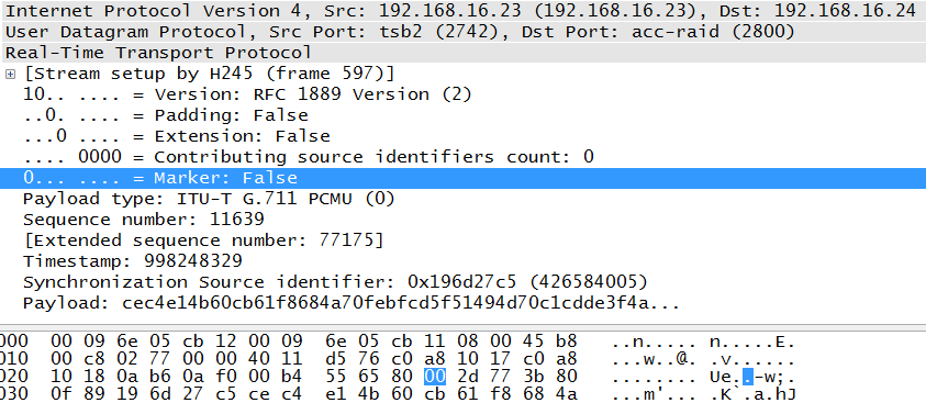
The next octet is also broken into two subfields: marker and payload type. Clicking on the marker bit locates this second octet for us. The second octet of the header begins with the highlighted field in Figure 4-6.
Following are the second octet field descriptions.
- Marker (M)
The simple definition of this single-bit field is that the marker allows important event such as a frame boundary to be marked. But the use of a marker is defined by a profile. RFC 3551 provides the following guidance:
For applications which send either no packets or occasional comfort-noise packets during silence, the first packet of a talkspurt, that is, the first packet after a silence period during which packets have not been transmitted contiguously, SHOULD be distinguished by setting the marker bit in the RTP data header to one. The marker bit in all other packets is zero.
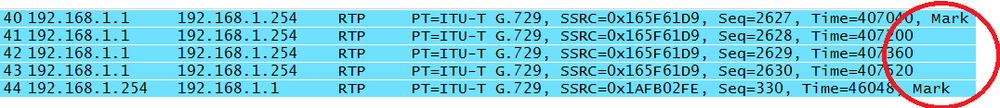
As discussed earlier, not all aspects of the protocol are implemented in the same way. So, some vendors may have a reason for delimiting the RTP stream by setting the marker bit to one, but it is common for the bit to be unused and therefore set to zero. The example shown in Figure 4-7 comes from a Cisco topology. For the packets beginning the sample voice conversation, we can see that both of the âtalkspurtsâ have the marker bit set.
- Payload Type (PT)
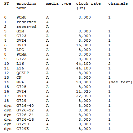
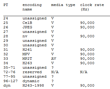
This is a 7-bit field that tells the receiver the format of the data contained in the packet. This value gives us the numerical value of the source codec used for the samples. Low values (0-23) are for the audio codecs, and the higher values are commonly for video, although other payload types may also be present. For example, RFC 4733 (RFC 2833) describes several DTMF payloads using a variety of IDs. We can see from the collection of packets in Figure 4-7 that the RTP packets contain data that was encoded with G.729. The packet shown in Figure 4-6 is encoded with the G.711 codec. RFC 3551 provides a list of the codecs defined up to the time of its writing. Some examples from Table 4 of RFC 3551 include the following (Figure 4-8):
As an example, PT 0 (PCMU) is for the G.711 codec, which encodes via pulse code modulation μ-law, and these can be seen in both the table and the previous packets. From RFC 3551 Table 5, we get the list of video codec types (Figure 4-9):
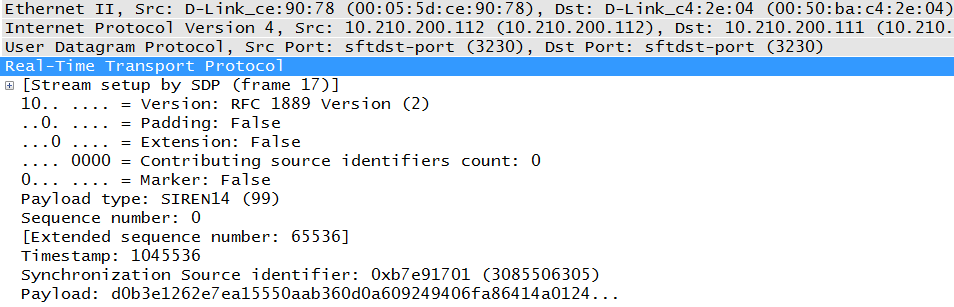
Specifying the value provides the receiver with the exact codec used. Other values can be used for dynamic, or source-defined, codecs. At the bottom of Figure 4-9, we can see the values assigned to dynamic codecs. Of course, using a dynamic RTP payload value like the one seen in Figure 4-10 from a Polycom endpoint can make it more difficult on the receiver because it must know the code. This also means that this information must be negotiated prior to the beginning of the RTP stream.
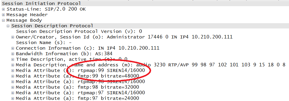
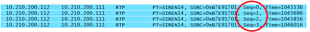
In this case, the payload type was negotiated via the Session Description Protocol (SDP), a portion of which is shown in Figure 4-11. SDP is a part of the SIP protocol, and the circled value of 99 tells the parties involved that the SIREN codec is to be used. On a separate topology, this value might be used again but for a completely different codec.
Now that the first couple of octets are out of the way, letâs move on to the rest of the fields.
- Sequence numbers
This 2-byte field contains the number referencing a particular packet and can help in detecting lost packets and placing the packets in the correct order. However, we have to remember that these are part of a UDP stream, and so sequencing is not tightly controlled by the host. These numbers increase by one for each packet sent by the same source. RFC 3550 recommends that these numbers start at a random value to make them less predictable. The packets shown in Figure 4-5 and Figure 4-6 is part of a much larger collection of packets in the audio stream, and the sequence numbers can be followed by looking at them together.
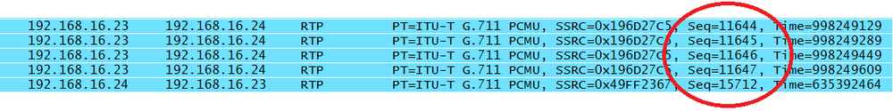
To make this discussion a little easier to follow, Iâll use the same series of packets. Remember that a call has been made from 111-1111 (192.168.16.23) to 111-2222 (192.168.16.24). Figure 4-12 starts us off.
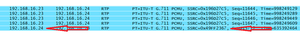
The sequence numbers for the first four RTP packets begin with 11644 as the random number and progress to 11647. Note that a voice call consists of two unidirectional streams, and the sequence numbers for the two streams have a different base value. The last packet contains a sequence number that is part of a stream heading in the opposite direction. As can be see by examining the Polycom captures in Figure 4-13, not every vendor follows the randomizing rules, as the sequence numbers in this particular packet stream begin with zero.
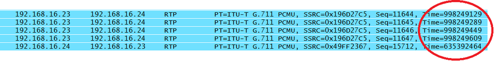
- Timestamp
The timestamp is the clock value at the sampling time of the packetsâ first octet. The accuracy of this 32-bit field is entirely dependent on the clock. The clock used is not the system clock but a timing function of the codec sampling. The requirements for the clock are stringent, as it is used in the calculations regarding the data stream, most notably the voice (or video) data packets and jitter. For example, per RFC 3551 a G.729, voice frame is 10 milliseconds and contains 80 bits. The default packetization is 20 milliseconds, or two G.729 frames per RTP packet. G.711 is always transmitted in 8-bit samples, each one an eight-thousandth of a second in duration. The RTP clock is based on the number of samples per second. Thus, a 20-millisecond frame contains 160 G.711 samples. Examining the timestamps for the same packets, as in Figure 4-14, shows us that the timestamp increases along these lines.
Whatever the method, packets or time periods, the size of the data chunks must fit into the payload and break across whole-number octets. The timestamp can also be used to calculate arrival times. Jitter measures variation in arrival time.
- Synchronization Source Identifier (SSRC)
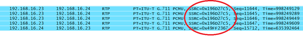
This field is a random identifier for the source of the real-time stream. It is not based on the network address. This 4-byte value groups the packets for playback. The idea is that sources involved in the RTP stream(s) will not be given the same value. RFC 3550 even provides a sample algorithm that might be used to generate the random number. From the same packet list, all of the packets from 192.168.16.23 have the same synchronization source identifier (Figure 4-15).
We can see that as soon as the source IP address changes, the synchronization source does too (Figure 4-16).
- Contributing Source Identifier (CSRC)
If there are any other data sources in the current RTP stream, their identifiers are listed here. Earlier in this chapter we saw the âcontributing source identifiers countâ field. With a single source, that field would be zero. Multiple sources are used when mixing or multiplexing sessions.
Note
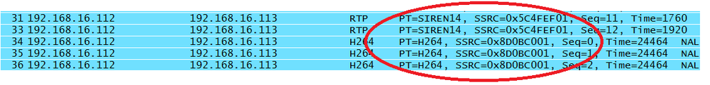
When audio and video are coming from the same node, different synchronization source identifiers are used to prevent confusion between the data formats. This also allows conversion from one codec to another. So, even if two nodes are communicating via audio and video stream through a single application, as is the case when Skyping with a webcam and microphone, it is likely that different synchronization sources will be used. Figure 4-17 depicts an example.
In Figure 4-17, the packets come from a Polycom videoconferencing client, and we can see that all of these packets are coming from 192.168.16.112 but two codecs are being used. Thus, the two source identifiers, timestamps, and sequence numbers separate the streams.
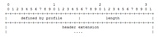
As mentioned earlier in this chapter, the RTP header has an extension bit. Should this bit be set, the RTP header expands to include the information required by the application. Only one extension header is permitted. The extension header from RFC 3550 is shown in Figure 4-18.
However, the use of this extension header is unusual, as the profile document (RFC 3551) provides the methodology normally used to manipulate the header based on the needs of the application. In fact, none of the topologies used in the writing of these chapters included an extension header. This is not to say that an RTP fixed header is limited to what we have seen so far. Other documents provide additional mechanisms for handling signals and sounds that may be needed on communication systems. For example, RFC 4733 outlines what must be done to send dual-tone multifrequency (DTMF) signals on VoIP systems. An example of this encapsulation is shown in Figure 4-19.
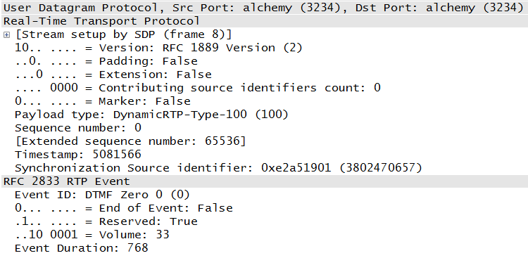
This packet references RFC 2833, which was superseded by RFC 4733. RFC 4733 describes how to carry traditional signaling in RTP packets. For example, instead of sending a packet to the call server that includes the number to be dialed, a telephone might take the DTMF sounds and convert them to RTP packets in the same way voice is captured.
RTCP packets and their identifiers are separate from the RTP values because the RTP synchronization source IDs may change. Instead, RTCP uses a canonical name, or CNAME. All of the participants are supposed to send RTCP packets, but if you have read through this book, you know that this is not reality. For example, Skinny-based deployments do not use RTCP at all. Additionally, vendors implement both RTP and RTCP differently, and so network behavior is not as predictable as we might wish.
The RTP control protocol (sometimes referred to as the real-time control protocol), has the primary goal of feedback on the quality of the RTP stream. It is common for VoIP to be described as simply another application running on the network. But it is a critical application, and so it is just as common to allocate network resources to handle real-time data. RTCP can provide information regarding the success of these network settings. The packet capture from the call indicates that RTCP packets are mixed in with the RTP packets, as shown in Figure 4-20.

The idea is that the senders provide information about the RTP stream, and the receivers provide feedback to the sender. This is accomplished via the sender and receiver report messages, which are sent as often as the bandwidth will allow. The whole point of this exchange is to provide feedback on the quality of the call. Senders and receivers can exchange the number of bytes or packets along with the timing values to obtain the current performance metrics.
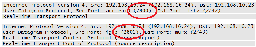
RTCP is also encapsulated in UDP. The port used by RTCP is dependent upon RTP; the two protocols are supposed to use sequential ports, as indicated in Figure 4-21.
One of the other functions of RTCP is to give each participant a canonical name, or CNAME. This is separate from the synchronization source ID (SSRC) because the SSRC can change over the course of a transmission. The CNAME does not. The Source Description message contains the CNAME. All told, there are five different RTCP message types: Sender Report, Receiver Report, Source Description, BYE, and Application Specific. From the RFC (Table 4-1):
Table 4-1. RTCP messages
| Abbreviation | Name | Value |
|---|---|---|
| SR | Sender Report | 200 |
| RR | Receiver Report | 201 |
| SDES | Source Description | 202 |
| BYE | Goodbye | 203 |
| APP | Application-defined | 204 |
Like RTP, RTCP messages begin with a fixed header. RTCP packets are also stackable, which allows them to be compounded. An example can be seen in the Sender Report packets, which also include the Source Description. Based on the requirements of knowing the CNAMEs and obtaining performance information, RFC 3550 requires the RTCP messages to be compounded packets. The first packet in the compound packet must be a report. Letâs take a closer look at the individual messages.
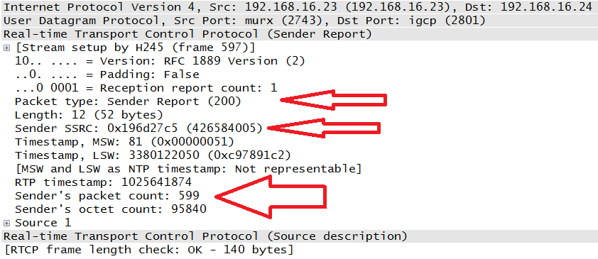
- Sender Report (SR) and Receiver Report (RR)
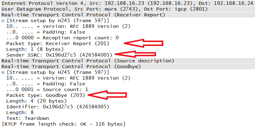
These messages contain transmission and reception statistics from an active sender or an inactive receiver. Examples can be seen in Figure 4-22 and Figure 4-23. The arrows in the packet capture indicate the packet type (200 for the Sender Report and 201 for Receiver Report) as well as the Synchronization Source ID. Note that both of these packets came from the same IP address: 192.168.16.23. Since this was a bidirectional conversation, both phones act as a sender and receiver. Each of the SR and RR packets contains the values helpful to determining the quality of the call. Timestamps, packet count, octet count, lost packets, and jitter values are all present.
Figure 4-23 also happens to contain an RTCP BYE message coded with type 203.
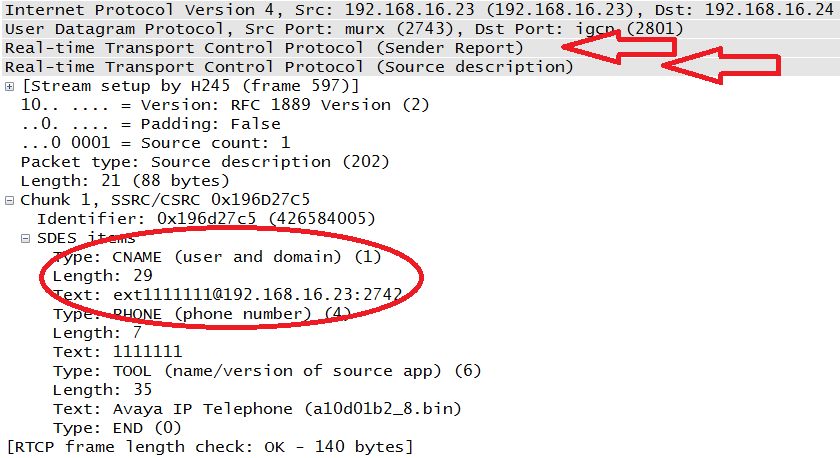
- Source Description Items (SDES)
The packets shown in Figure 4-22 and Figure 4-23 are compound packets. In case you missed the headers, Figure 4-24 points them out. In the case of the Sender Report, the second packet is the Source Description, or SDES. Figure 4-24 also depicts an expansion of this section from the same message seen in Figure 4-22. This time the Sender Report portion has been collapsed. The CNAME is circled.
With the SDES message, all receivers will know the CNAME of the endpoint, its phone number, and the actual endpoint unit being used in the transmission. Table 4-2 lists SDES types from the RFC.
- BYE
Figure 4-23 also includes the Receiver Report with the compounded BYE (Goodbye) message. The requirement here is that the BYE message be the last message sent with a particular SSRC or CSRC. Upon receipt of the BYE packet, the synchronization source ID is removed from the participant list.
- APP
This particular RTCP message is called the Application Defined packet. It is intended for experimental use.
RFC 3550 spends a good amount of time discussing the proper rate at which RTCP packets should be generated. Added challenges to selecting the proper rate include questions about affecting the performance of the RTP stream, getting the CNAME information to all participants, scaling of the connections when there are many users, and multicasting. From the RFC:
It is RECOMMENDED that the fraction of the session bandwidth added for RTCP be fixed at 5%. It is also RECOMMENDED that 1/4 of the RTCP bandwidth be dedicated to participants that are sending data so that in sessions with a large number of receivers but a small number of senders, newly joining participants will more quickly receive the CNAME for the sending sites.
According to the RTCP Sender Report (Figure 4-22) from the phone at 192.168.16.23 (extension 111-1111), a total of 599 RTP packets were sent. The phone at 192.168.16.24 (extension 111-2222) sent a total 427 RTP packets; this packet is not shown here. By contrast, each node only about 14 RTCP packets, well below the RFC 3550 recommendation. However, this is just one topology and a small one at that. RFCs 3550 and 3551 also leave room for the profile to specify the report interval. On an Avaya system like the one used in this network, the RTCP report interval is commonly set to five seconds. Other than the percentage of session bandwidth noted above, the recommended transmission rate recommended by the RFC is a minimum of every five seconds.
Certainly one of the objects of an attack is a replay of VoIP-based transmissions. In order to accomplish this, attackers would need access to the RTP stream. Unfortunately, the same mechanism that allows a receiver to understand the encoding mechanism used by the sender also allows the attacker to decode the stream. Each packet contains the payload ID, which identifies the codec. The synchronization source identifier allows the receiver (and attacker) to collect packets from the same source, and the sequence numbers keep them in order.
Once the packets are collected and ordered, it is a simple matter to play them back. Figure 4-25 displays the player built into Wireshark. The player is activated after selecting a single RTP packet and performing an RTP-stream analysis from the Telephony menu.
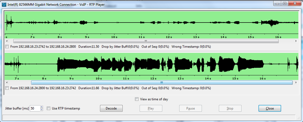
The BackTrack distributions and Wildpackets Omnipeek also have the ability to collect packets and play them back.
How does an attacker get access to the RTP stream? The proliferation of wireless networks also leads to the proliferation of wireless endpoints, such as phones. Attacking a wireless network is straightforward: capture the traffic. The same tools that provide a player also have the ability to capture wireless frames. But even without access to the wireless network, or if the wireless network is encrypted, an attacker can sometimes gain access to the RTP streams by attacking infrastructure devices. Two popular methods are overflowing the source address table on a switch and spoofing a trunk port on a switch.
With source address table flooding (also known as MAC address table flooding), the switch memory is constantly filled with MAC addresses such that valid addresses cannot be added to the table. Traffic destined for these valid MAC addresses must be flooded out of all ports. Spoofing a trunk port is an attack in which the target switch is fooled into believing that a trunk line is connected. Traffic destined for unknown MAC addresses is flooded down trunk ports like broadcast traffic. The attacker can also send traffic to specific destinations by tagging traffic and VLAN hopping. Attacks against hosts can trick them into sending traffic to the attacker or allowing the attacker to act as a man in the middle.
In the face of these challenges, RTP streams must be encrypted in order to protect their privacy. RFC 3711 describes the Secure Real-Time Transport Protocol, or SRTP. RFC 3711 also defines SRTCP and therefore has provisions for the privacy and authentication of both RTP and RTCP messages.
Secure RTP is considered a profile of RTP. Thus, it modifies RTP slightly to suit its purposes. SRTP and SRTCP use the same structure as RTP and RTCP, with the addition of the information allowing the additional functions. Figure 4-26 depicts the packet structure.
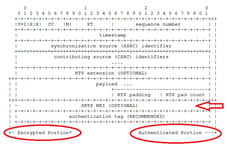
The SRTP packet shares the entire RTP header, adding the fields indicated by the arrow. We can also see that while the entire packet is authenticated, only a part is encrypted. STP fields include:
- Master Key Index
This is an optional field that can be used to provide information about which master key is to be used.
- Authentication Tag
The field is used to provide the value calculated by the authentication algorithm.
RFC 3711 has predefined keys and algorithms (though others are supported) for use in a secure deployment. For encryption, the âdefault cipherâ is the Advanced Encryption Standard, or AES. For authentication, the Hashed Message Authentication Code â Secure Hash Algorithm 1 (HMAC-SHA1) is specified. There are two keys used: a master and session key. Endpoints and the call server use the master key to derive the session. The session keys are those actually used to encrypt the voice or video data. The RFC does not specify key distribution. This is often handled by the signaling protocol.
The idea is that the endpoints maintain what is called the âcryptographic context,â or information about the algorithms, keys, and the current state of the connection. But endpoints also keep track of rollover counters (which count the reuse of sequence numbers), replay lists, and any salt keys. Salting adds extra material to the session generation process in order to make the session key more difficult to derive externally. SRTP and SRTCP share the same master key and cryptographic context but typically do not use the same session keys. Figure 4-27 depicts the SRTCP structure described by RFC 3711.
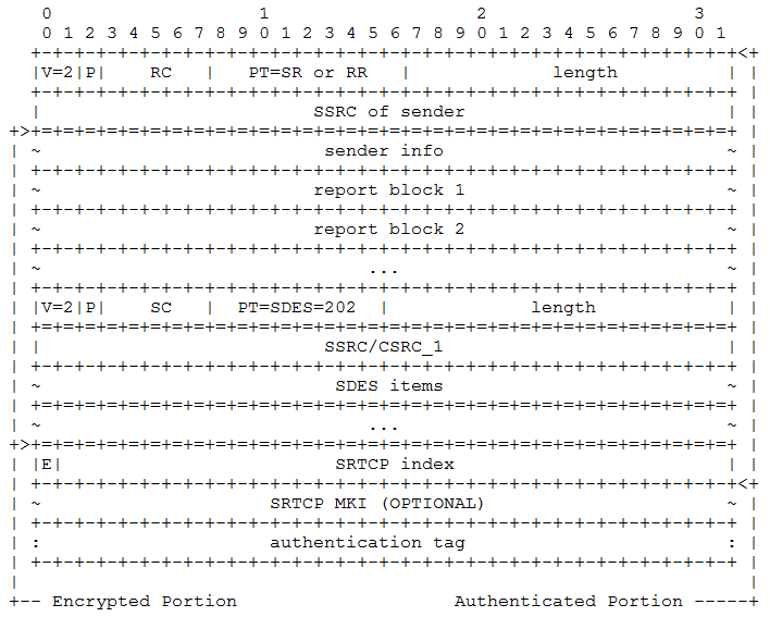
Again, we can see the shared structure of the packet. The entire message is authenticated, but only the data about the stream is encrypted. The MKI and authentication tag fields serve the same purpose as they did in SRTP.
Note
Not all vendors support SRTP and SRTCP. Even for those that do, it is often the case that in a mature environment, endpoint devices have varying levels of support for features or encryption requirements. Lastly, some of these items differ between vendors. If you want to encrypt media transmissions in real-time streams, you should thoroughly examine the planned deployment with an eye toward the SRTP profile. An argument can be made that encryption is not necessary because most VoIP endpoints are wired and internal. This is necessarily a local decision, but the presence of wireless networks, hosted solutions, guest access, telecommuters, or other situations in which the RTP streams may be exposed argue for a close examination of the network specifications.
VoIP signaling protocols handle such items as registration, address signaling, establishing logical channels, and call termination. However, they do not transport voice or video (real-time) data. Most VoIP communication systems rely on RTP for this purpose. RTP provides encapsulation for this data, sequencing, time-stamps, and identification for all of the packets that are part of the real-time stream.
In order to better understand the quality and performance of the connection, RTCP is part of the RTP deployment. RTCP carries data about information such as timing and packet count between the senders and receivers. Both of these protocols are described in RFC 3550. A companion document to RFC 3550 is RFC 3551, which describes the profiles used in conjunction with RTP. Profiles allow media streams to provide additional fields to the RTP header that may contain flow-specific parameters.
RTPâs cleartext nature can open it up to attacks such as replay, meaning that attackers can collect the RTP packets and play back the conversation. In order to help defend against this, Secure RTP (SRTP) and Secure RTCP (SRTCP) were defined in RFC 3711. This RFC provides for the encryption of the real-time data and authentication of the messages.
This chapter explains the structure and operation of RTP and RTCP through the use of packets caught on a VoIP network.
- RFC 3550 (obsoletes RFC 1889)
- RFC 3551 (obsoletes RFC 1890)
RTP Profile for Audio and Video Conferences with Minimal Control
- RFC 3711
- RFC 4733
RTP Payload for DTMF Digits, Telephony Tones, and Telephony Signals
- RFC 5506
Support for Reduced-Size Real-Time Transport Control Protocol (RTCP): Opportunities and Consequences
- RFC 5761
- RFC 6051
- RFC 6222
Guidelines for Choosing RTP Control Protocol (RTCP) Canonical Names (CNAMEs)
True or false: most communication systems use RTP when transporting voice and video data.
True or false: RTP has a build in quality of service mechanism.
How are RTP streams differentiated from each other?
True or false: the ports for RTP and RTCP are random.
What is the payload type for a G.729 encoded packet?
What are the five RTCP message types?
What is the primary purpose of RTCP?
In what packet can the canonical name be found?
True or false: RTCP is tied to the RTP stream by using the same synchronization source ID.
What is a common rate at which RTCP packets are transmitted?
True.
False.
Using the synchronization source identifier.
The selection of the RTP port is random, but the RTCP port is supposed to be the next highest odd-numbered port.
18.
Source Report, Receiver Report, Source Description, Bye, and APP.
To provide performance feedback on the RTP streams.
Source Description.
False.
Every five seconds.
This chapter is supported by the book website. So, if the activity lists equipment or software that you do not have, go to the book website for additional content.
The point of this activity is to build a topology capable of generating RTP and RTCP packets. This can be done via a topology with a call manager at its center or via point-to-point connections using VoIP soft clients. For example, this book typically uses topologies with a call server but occasionally uses captures done with just a pair of Polycom soft clients (Figure 4-28).
Materials: two VoIP endpoints (software or hardware), call server (optional), Wireshark
Once the topology is built, start a capture on either the soft-client endpoints or the monitor stations watching the VoIP phones.
Make a phone call between the VoIP endpoints.
Ensure that the capture obtains the packets necessary for the next couple of activities.
Materials: captures from the previously built topology
Within Wireshark, filter the packets using RTP (Figure 4-29).
From the RTP stream, identify the following items:
Payload type
Sequence numbers
Timestamps
Synchronizing Source Identifier
How do the sequence numbers advance? Are there contributing sources? How do the timestamps advance? Do any of the packets have markers?
Materials: captures from the previously built topology.
Identify the hexadecimal value of the payload type from these captures.
To what codec does the payload type correspond?
How does this codec work?
What are the bandwidth requirements of this codec?
What are the uses of this particular codec?
Materials: captures from the previously built topology.
Filter the packet captures for RTCP in the same way that you filtered for RTP.
Analyze the RTCP packets for the four basic message types: Source Report, Receiver Report, Source Description, and APP.
Open each of these packets and identify the fields in each. What are the packets trying to tell you?
Get Packet Guide to Voice over IP now with the O’Reilly learning platform.
O’Reilly members experience books, live events, courses curated by job role, and more from O’Reilly and nearly 200 top publishers.

