Chapter 4. VLANs and Trunking
The move from hubs (shared networks) to switched networks was a big improvement. Control over collisions, increased throughput, and the additional features offered by switches all provide ample incentive to upgrade infrastructure. But Layer 2 switched topologies are not without their difficulties. Extensive flat topologies can create congested broadcast domains and can involve compromises with security, redundancy, and load balancing. These issues can be mitigated through the use of virtual local area networks, or VLANs. This chapter provides the structure and operation of VLANs as standardized in IEEE 802.1Q. This discussion will include trunking methods used for interconnecting devices on VLANs.
Problem: Big Broadcast Domains
With any single shared media LAN segment, transmissions propagate through the entire segment. As traffic activity increases, more collisions occur and transmitting nodes must back off and wait before attempting the transmission again. While the collision is cleared, other nodes must also wait, further increasing congestion on the LAN segment.
The left side of Figure 4-1 depicts a small network in which PC 2 and PC 4 attempt transmissions at the same time. The frames propagate away from the computers, eventually colliding with each other somewhere in between the two nodes as shown on the right. The increased voltage and power then propagate away from the scene of the collision. Note that the collision does not continue past the switches on either end. These are the boundaries of the collision domain. This is one of the primary reasons for switches replacing hubs. Hubs (and access points) simply do not scale well as network traffic increases.

Figure 4-1. Before and after collision
The use of switches at Layer 2 eliminates much of the scaling
problem because they filter out problems such as collisions. Instead,
transmissions are now governed by the behavior of the switches and the
broadcast domain. A broadcast domain defines the area
over which a broadcast frame will propagate. For example, an ARP request
issued by PC 3 results in a broadcast frame that propagates through the
switches all the way to the routers as shown in Figure 4-2. A broadcast frame has the broadcast address
(FF-FF-FF-FF-FF-FF) as the destination
MAC.
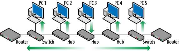
Figure 4-2. Broadcast domain
With the improved performance and filtering resulting from the use of switches, there is a temptation to create large Layer 2 topologies and add lots of nodes, but this creates a large broadcast domain. The problem is that all devices on a network (computers, printers, switching equipment, etc.) generate broadcast and multicast frames that traverse the entire broadcast domain, competing with data traffic for bandwidth. Much of this traffic is for management of the network and includes protocols for address resolution (ARP), dynamic host configuration (DHCP), spanning tree (STP), and an assortment of Windows tasks. Figure 4-3 illustrates the potential difficulty. Assume that PC1 has generated the following requests: ARP, Windows registration, and DHCP.
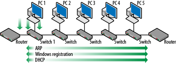
Figure 4-3. Broadcast frame growth
Because all of the requests use a broadcast frame, as they are received at Switch 1, the frames are forwarded in all directions. As the other switches in the topology follow suit, the frames traverse the entire network and are received at all other nodes and the routers.
As the number of network nodes increases, the amount of overhead also increases. Each switch might be connected to dozens of nodes, with each node generating the several broadcast frames. If enough traffic is created, even a switched network can have poor performance. Deploying VLANs can help solve this problem by breaking up the broadcast domain and separating the traffic.
What Is a VLAN?
A virtual local area network (VLAN) is a logical grouping of ports which is independent of location. A single VLAN (and the nodes connected in a single VLAN) will behave in the same way as if it was a separate Layer 3 network. VLAN membership need not be limited to sequential ports or even ports on the same switch. Figure 4-4 depicts a very common deployment in which nodes are connected to a switch and the switch is connected to a router. Looking at the left side, the automatic assumption would be that all of the nodes are on the same IP network since they all connect to the same router interface.
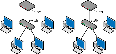
Figure 4-4. Basic switch and VLAN topology
What is not obvious from the topology on the left is that by default, all of these nodes are actually part of the same VLAN. So, another way to think about this topology is based on the VLAN as shown on the right. For example, with Cisco devices the default VLAN is VLAN 1. This is also called the management VLAN. Its initial configuration includes all ports as members and this reflected in the source address table or SAT. This table is often described as being used to forward frames to the proper Layer 2 port based on the destination MAC. With the introduction of VLANs, the source address table reflects the port to MAC address mapping on a per-VLAN basis resulting in more advanced forwarding decisions. Figure 4-5 displays the output from both the show mac-address-table and show vlan commands. All of the ports (Fa0/1 – Fa0/24) are in VLAN 1.
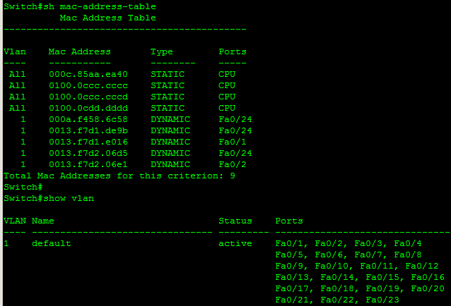
Figure 4-5. Switch SAT and VLAN output
Another common topology can be seen in Figure 4-6 in which two switches are separated by a router. In this case, a group of nodes are connected to each switch. The nodes on a particular switch share a common IP addressing scheme. There are two networks, 192.168.1.0 and 192.168.2.0.
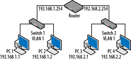
Figure 4-6. Router, switch and VLANs
Note that both of the switches have the same VLAN since, in the absence of any configuration changes, switches from the same vendor will have the same numbering convention. Nonlocal network traffic must be sent to the router for forwarding. Routers will not forward Layer 2 unicast, multicast and broadcast frames. VLANs provide a very similar logical topology in that nodes within a VLAN share a common addressing scheme and that nonlocal traffic (traffic destined for nodes on a different VLAN) must be sent to the router for forwarding. By creating an extra VLAN on one of the switches and removing the other, Figure 4-6 can now be redrawn as shown in Figure 4-7.

Figure 4-7. Single switch, multiple VLANs
A VLAN operates in the same way as a Layer 3 IP-based network. Thus, nodes on the 192.168.1.0 network must go to the router when trying to communicate with nodes on the 192.168.2.0 network even though all of the computers are connected to the same switch. In order to communicate between VLANs, routing functionality must be part of the topology. Layer 2 unicast, multicast and broadcast traffic will not cross VLAN boundaries, therefore traffic generated on VLAN 1 will not be seen by nodes on VLAN 2. Only the switch is aware of the VLANs. The nodes and the router have no idea that VLANs are in use—they are “non VLAN-aware.” With the addition of the routing decision, Layer 3 functionality can now be leveraged for additional security settings, problem/traffic containment and load balancing.
The Effect of VLANs
Configuring a switch for multiple VLANs reduces the size of each broadcast domain. Therefore the amount of overhead traffic is lower which reduces bandwidth competition with data traffic. Stated another way, a node in a particular VLAN has less broadcast traffic with which to contend. Since switch forwarding behavior is based on MAC addresses stored in the source address table, the following rules apply:
For known unicast destinations, the switch will forward the frame to the destination port only.
For unknown unicast destinations, the switch will forward the frame to all active ports except the originating port. This is called flooding.
For multicast and broadcast destinations, the switch will forward the frame to all active ports except the originating port.
However, the switch now has the additional requirement of considering the VLAN of the destination node. Referring to Figure 4-7, if PC1 were to issue an ARP request, instead of simply forwarding this frame to every port, the switch determines that the frame originated on VLAN 1. The result is that only PC2 and the leftmost router interface (192.168.1.254) actually see the frame.
Aims and benefits from the 802.1Q standard:
VLANs are supported over all IEEE 802 LAN MAC protocols, over shared media LANs as well as point-to-point LANs.
VLANs facilitate easy administration of logical groups of stations that can communicate as if they were on the same LAN. They also facilitate easier administration of moves, adds, and changes in members of these groups.
Traffic between VLANs is restricted. Switches forward unicast, multicast, and broadcast traffic only on LAN segments that serve the VLAN to which the traffic belongs.
As far as possible, VLANs maintain compatibility with existing switches and end stations.
If all switch ports are configured to transmit and receive untagged frames (frames to/from non-VLAN aware devices), switches will work in plug-and-play ISO/IEC 15802-3 mode. End stations will be able to communicate throughout the Bridged LAN.
VLAN Ports Do Not Need to be Continuous
Since VLANs are logical groupings of nodes that are independent of location, it does not matter where the nodes connect. Figure 4-8 demonstrates this concept. The topology in Figure 4-7 has been redrawn with the IP addresses of network nodes changed. To help with clarity, in this example VLAN 1 is also red and VLAN 2 is blue. Ports 1, 4 and 5 are part of red VLAN 1 while ports 2, 3 and 6 are part of the blue VLAN 2.
It is often the case that network technicians do not wish to rewire the topology every time that a new node is connected. So, a host may simply be connected to any available port and the port is then assigned to a particular VLAN. The critical idea is that the behavior is the same whether or not the ports are right next to each other. Thus, PC1 and PC4 can communicate directly with each other but must use the router to get to PC2 and PC3. Frames issued on red VLAN 1 will not be seen by nodes on blue VLAN 2.
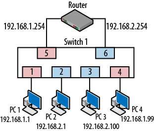
Figure 4-8. Noncontinuous VLANs
Types of VLANs
There are two types of VLANs: static and dynamic. Both of these types can be used to cover small or large geographic areas. The type of VLAN that has been discussed thus far (a single switch divided into multiple VLANs) is called a static VLAN. Membership is largely determined by geographical location and to which port a particular node is connected. Most of the nodes in a particular VLAN are likely to be located in the same building, floor or set of offices. These VLANs can also be thought of as having local membership.
Figure 4-9 depicts an example of how nodes and VLANs might be arranged. PC1 and PC2 are physically located in the same part of the building and so are assigned to the same VLAN. The same is true for PC3 and PC4. It is likely that they serve users from the same department. This type of topology is configured manually by a network administrator who assigns ports on the switch to a particular VLAN. Again, the nodes and router do not have any knowledge about the VLANs.

Figure 4-9. Static VLAN, local membership
Most VLANs are configured with static membership. In topologies like those described above, nodes remain connected to the same port and so there is no need to change VLAN membership. The desktop computer is usually associated with an office desk or cubicle assigned to an employee so there is little need to worry that the machine will move.
There are times when nodes do move around. There may be a need to access different resources. Ports may be used by different departments at different times or differing levels of security may be required. Dynamic VLANs are more appropriate for these situations. Dynamic VLANs allow nodes to move around without altering VLAN membership. This means that as they plug into a particular port, the switch automatically configures the port for membership in the correct VLAN. A port that was configured for access in VLAN 1 for node A may now switch to VLAN 2 for node B. Consider the case in Figure 4-10. PC4, now a laptop, is moved from a port in VLAN 2 to a port in VLAN 1.

Figure 4-10. Moving from one VLAN to another
Case 1—DHCP
If DHCP has been deployed, when PC4 moves, it will simply obtain a new IP address on the new network, though this is not guaranteed. This may actually be the most common behavior for nodes connecting to a network on a particular VLAN. However, if services or security measures are in place and the organizations’ policy is to maintain separation between VLANs, then this configuration may pose a problem—access to the server. Once on the new network, PC4 may no longer be able to reach the correct server or may require additional configuration to support the move.
Case 2—No DHCP
If the IP address of PC4 is statically configured, when it moves to the new location, its IP address will not match the network. It will no longer be able to reach the IP address of the gateway or the server. In this case, the node will not have any connectivity at all.
Solution: Dynamic VLANs
However, if the switch is smart enough to recognize that PC4 has now moved to a new port, it may be able to automatically repair the connection. Once PC4 connects to the new port, it will generate traffic. Upon receipt of a frame from PC4, the switch completes a database look up to determine the VLAN membership and then will assign the port to the proper VLAN. Once this has occurred, PC4 will be able to communicate just as it did before the move. The new topology would look like the one shown in Figure 4-11. The node will not even have to change its IP address.
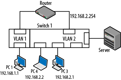
Figure 4-11. New dynamic VLAN topology
But how does the switch know? The most common method of assigning dynamic VLAN membership is via the MAC address. As soon as the node generates a single frame, the switch completes the MAC address query and then assigns the port. The nodes still do not have any knowledge that VLANs are used. VLAN membership can also be based on other criteria or tied to authentication schemes such as 802.1X.
VLANs Between Switches
So far, the VLANs discussed have been deployed on a single switch. The question arises: “What happens if multiple switches are part of the overall network fabric? How does it work?” The answers depend on the switch configurations. A default topology is shown in Figure 4-12 where two switches have simply been powered up and several nodes connected. The default VLAN for both switches (if we assume Cisco devices) will be VLAN 1. This also means that the connections running between the switches will also be in VLAN 1. The router provides the egress point for all nodes.
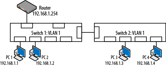
Figure 4-12. Multiple switches, single VLAN
In this default topology, the nodes will not have any trouble connecting to each other because the source address tables on the switches will show that they are all in the same VLAN. This will allow the unicast, multicast and broadcast traffic to flow freely. Note also that the nodes exist on the same IP network. The connection between the switches uses either a crossover cable or an uplink port.
Problems occur when new VLANs are created as shown in Figure 4-13. Since the VLANs create Layer 3 boundaries around the ports connected to the hosts, they are not able to communicate.
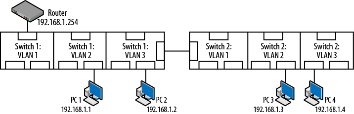
Figure 4-13. Problems with additional VLANs
Examining Figure 4-13, there are a couple of problems. First, the computers are all on the same IP network, despite being connected to different VLANs. Secondly, the router is isolated from all of the nodes because it is in VLAN 1. Lastly, the switches are interconnected via different VLANs. Each of these would create communication difficulties, but taken together, there is little or no communication between network elements.
It is often the case that a switch may be full or that nodes within the same administrative unit are geographically separated from each other. In these cases, a VLAN can be extended to neighboring switches through the use of a trunk line. Trunks will be discussed in greater detail later in this chapter, but for now it is sufficient to say that trunks connecting separate switches can, among other things, convey VLAN information between network devices. Figure 4-14 suggests several changes to repair the items noted in Figure 4-13.
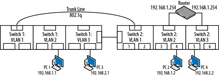
Figure 4-14. Topology repaired with trunking
Repairs to the topology include:
PC1 and PC2 have been assigned to the 192.168.1.0 network and VLAN 2
PC3 and PC4 have been assigned to the 192.168.2.0 network and VLAN 3
The router interfaces are connected to VLANs 2 and 3.
The switches are interconnected via trunk lines.
Note that while the trunk ports appear to be in VLAN 1, they are not as denoted by the letter T. Trunk ports do not have membership in any particular VLAN. Now that the VLANs persist across multiple switches, the nodes can be physically located anywhere and still be members of the same VLAN. When several switches are configured with VLANs and ports maintain their VLAN membership, the architecture is referred to as “end-to-end” and “static.” It is not uncommon to have these switches located in different wiring closets, or even different buildings. Switches in the same closet can also be interconnected via trunk lines.
What is a Trunk?
Generally, there are two ways to look at a trunk line. In telephony, the term trunk refers to connections between offices or distribution facilities. These connections represent an increased number of lines or time division multiplexed connections as shown in Figure 4-15. Examples include 25 pair bundles or T carriers.
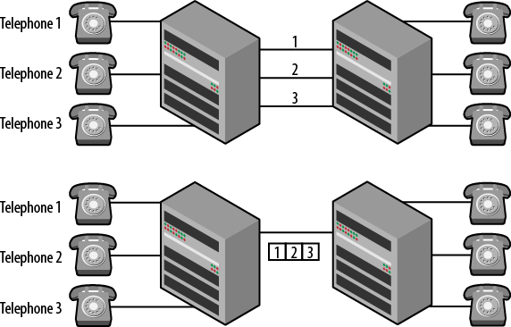
Figure 4-15. Telephone lines and trunks
For data networking, trunks have little to do with increasing the number of connections between switches. The primary use of a trunk line in a data network is to convey VLAN information. The trunk line shown in Figure 4-14 carries VLAN and quality of service information for the participating switch.
When a trunk line is installed, a trunking protocol is used to modify the Ethernet frames as they travel across the trunk line. In Figure 4-14 the ports interconnecting the switches are trunk ports. This also means that there is more than one operational mode for switch ports. By default, all ports are called “access ports.” This describes a port used by a computer or other end node to “access” the network. When a port is used to interconnect switches and convey VLAN information, the operation of the port is changed to a trunk. For example, on a Cisco switch the mode command would be used to make this change. Other vendors indicate that the port is now “tagged,” indicating that a VLAN id will now be inserted into the frames. The 802.1Q standard also includes a provision for “hybrid” ports that understand both tagged and untagged frames. To be clear, nodes and routers are often unaware of the VLANs and use standard Ethernet or “untagged” frames. Trunk lines providing VLAN or priority values will be using “tagged” frames. An example of a tagged frame can be seen in Figure 4-17.
So, on the trunk ports, a trunking protocol is run that allows the VLAN information to be included in each frame as it travels over the trunk line. For configuration, there are generally two steps: converting the port to trunk mode and determining the encapsulation (trunking protocol) to be used.
Using Figure 4-16 we’ll go through an example of two nodes communicating over a trunk line. There are several steps to the process (in addition to host routing) so Figure 4-16 is labeled based on the steps listed.
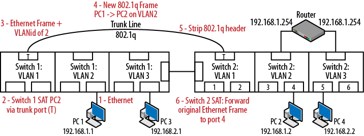
Figure 4-16. Trunking traffic between switches
PC1 sends traffic to PC2 after processing its host routing table. These nodes are in the same VLAN but they are connected to different switches. The basic process:
The Ethernet frame leaves PC1 and is received by Switch 1.
The Switch 1 SAT indicates that the destination is on the other end of the trunk line.
Switch 1 uses the trunking protocol to modify the Ethernet frame by adding the VLAN id.
The new frame leaves the trunk port on Switch1 and is received by Switch 2.
Switch2 reads the VLAN id and strips off the trunking protocol.
The original frame is forwarded to the destination (port 4) based on the SAT of Switch 2.
The packet shown in Figure 4-17 provides detail on this modification. In this particular case, the trunking protocol that has been used is IEEE 802.1Q. This frame is an ICMP echo request from PC1→PC2 and because it traverses the trunk line, the VLAN tag must be included so that Switch 2 knows how to properly forward the packet.
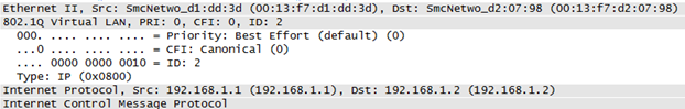
Figure 4-17. Ethernet frame with 802.1Q trunking
The Ethernet frame is intact but now has several additional fields such as the VLAN ID. In this case, the two computers communicating are on VLAN 2. The binary value of 0000 0000 0010 is shown. Note that the IP and ICMP headers have not been modified. However, because this is a change to the actual frame, the Cyclical Redundancy Check (CRC) at the end of the Ethernet frame must be recalculated. Trunking probably doesn’t get as much attention as it should but, as soon as VLANs are configured on the switches, a trunking protocol must be used if the VLANs are to persist from one switch to another. Without a trunk, the nodes will probably all be on the same VLAN which can lead to the problems noted earlier. Trunks and VLANs are a vital part of standard topologies.
Trunking Protocol Standards
There are two trunking protocols used on modern communication networks: Inter-Switch Link (ISL) from Cisco and the aforementioned nonproprietary IEEE 802.1Q. Of the two, IEEE 802.1Q is the industry standard. Even Cisco switches now use IEEE 802.1Q (dot1q) by default.
IEEE 802.1Q
The IEEE 802.1Q standard is actually entitled “IEEE Standards for Local and Metropolitan Area Networks: Virtual Bridged Local Area Networks” and is primarily concerned with VLANs themselves. The trunking protocol or “tagging” of frames is discussed in latter sections of 802.1Q. As a reminder, IEEE 802.1D is the standard for MAC Access Control Bridges upon which Layer 2 networks are constructed. Switch vendors adhere to both of these standards and then add enhancements such as management. The IEEE 802.1Q standard bases much of its language on documents such as the ISO/IEC 15802-3 standard for MAC bridges.
When using IEEE 802.1Q, a 4-byte header is inserted in between the Ethernet and IP headers. Per the 802.1D standard, it is inserted 12 bytes into the frame immediately following the source MAC address. Therefore, frame is actually changed. So, the Ethernet type, which indicates the kind of encapsulated data, must also change. As an example, IP packets have an Ethertype value of 0800 but when running over a trunk it is changed to 8100 as shown in Figure 4-18.
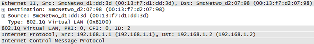
Figure 4-18. Ethertype for IEEE 802.1Q
The 802.1Q header is straightforward and includes the following fields:
- The tag protocol identifier (2-byte TPID)
- The value of 8100 can be seen just before the highlighted hexadecimal.
- The tag control information (2-byte TCI)
There are three ways that this information can be structured but those used in token ring and FDDI networks will not be covered here. The TCI includes the priority, Canonical Format Indicator and VLAN ID. The 2-byte hexadecimal TCI from Figure 4-18 is 20 65.
- Priority
Used in quality of service implementations, also called class of service. This is a three bit field with values ranging from 000 (0) to 111 (7). The default value is 0 though vendors recommend higher values for certain types of traffic. For example, VoIP traffic is typically set to binary 101 (base 10: 5). Figure 4-18 depicts a slightly elevated priority of 2. Figure 4-19 depicts prioritized traffic from another network. In this case, the priority is set to 111 (7).
- Canonical Format Indicator (CFI)
This single bit field was used to indicate bit orders or flags for routing information associated with legacy protocols such as token ring and FDDI. Today, almost all switching is Ethernet. So, the field is almost never used and the value is typically 0.
- VLAN ID
The last twelve bits are allocated for the VLAN ID for values ranging from 1 to 4095. The VLAN ID in binary is 1100101. This corresponds to VLAN 101 in base 10 numbers.
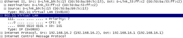
Figure 4-19. Tagged frame with priority field
Inter-switch link (ISL)
As this is an older Cisco proprietary protocol, not much time will be spent on its description. Figure 4-20 shows an ISL tagged frame and illustrates a different approach to tagging. IEEE 802.1Q performs what is called “internal tagging” by inserting the VLAN header in between the Ethernet and IP headers. This also forces a recalculation of the frame CRC. ISL prepends the tag. The ISL header is also considerably larger than the 802.1Q header and does not provide for priority handling. Modern Cisco equipment uses IEEE 802.1Q as the default trunking and tagging protocol.
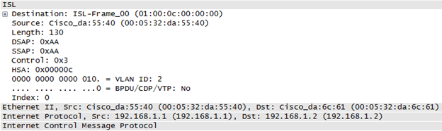
Figure 4-20. ISL tagged frame
Pruning
While a particular VLAN may extend well beyond a single switch and may exist throughout much of a topology, it is not necessary to have it persist on every switch.
In Figure 4-21, VLANs 1, and 2 exist on both Switches. But VLAN 3(yellow) only exists on Switch 1. It doesn’t make much sense to have the traffic for VLAN 3 forwarded to Switch 2. The benefits include a reduction in trunk line traffic and potential security improvement through this pruning capability, especially with static topologies. Switch 1 prunes VLAN 3 traffic (prevents passage) out its trunk port.
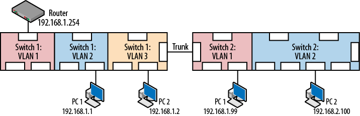
Figure 4-21. Pruning example
Vendors have different approaches to pruning; some permit all VLANs by default (Cisco), others deny all VLANs by default. Regardless of vendor, it is always a good idea to examine the trunking configuration and determine the best approach for tagged frames and untagged frames and pruning.
VLAN Design Considerations
VLANs create boundaries that can isolate nodes or traffic so some thought should go into the design of a multi-VLAN topology. The general question to ask is “Who is talking to whom and what are they trying to get done?” The following list provides some guidelines.
- Scaling considerations
How big is the network and how far does the traffic have to go?
- Traffic patterns
Over what pathways do packets/frames travel?
- Applications
Why is the traffic there? What are the hosts trying to do?
- Network management
Is SNMP or some other management protocol running? How will you get to all of the nodes?
- Group commonality
What do nodes have in common? Are there shared resources or traffic patterns?
- IP addressing scheme
What does the IP address space look like? How many nodes will be in each VLAN?
- Physical location
Do the nodes occupy the same office? Floor? Building?
- Static versus Dynamic
Are the nodes moving around or are they stationary?
- End-to-end versus Local VLANs
Are there nodes outside of a location that should be part of the same VLAN?
- 80/20 versus 20/80 traffic flow pattern
Is a majority of the flow internal or external? Is this pattern changing?
- Common security requirements
Are these nodes servers? End nodes? Wireless? Do the nodes represent vital company resources? Are these public facing machines?
- Quality of service
Are there quality of service concerns?
In addition to these general questions, there are other good practices to follow that will help reduce exposure to security risk and protect vital network resources.
Wireless should be in its own VLAN. Since wireless is a shared media, all broadcast and much of the multicast traffic coming from the switch will be shared as well. In addition, any flooded unicast traffic will be seen by all wireless nodes. Creating a VLAN for wireless nodes narrows the traffic that they can see. In addition, a potential attack via wireless will have a boundary to cross before reaching other portions of the network.
VoIP elements should also be in their own VLAN. This is as much for quality of service as it is for protection. Anytime real time voice traffic has to compete for bandwidth, there is the potential for performance degradation. Security concerns are to some extent relieved by the VLANs as well. Tools such as Wireshark can not only capture but decode and play voice traffic so it is important to keep voice traffic separated wherever possible.
Other important network devices such as servers or even users of sensitive data should be placed in their own VLANs. In addition to the reasons already stated, many vendors have features that allow the creation of VLAN specific security and QoS policies.
Security Considerations
This chapter has discussed the need to isolate traffic. Organizations need not forward data to every single port because this is inefficient and represents a security risk due to potential eavesdroppers. There are several configuration items that should be part of any VLAN deployment checklist. One of the biggest challenges associated with deploying a network device is understanding default behavior. Switches and routers are no different, particularly as the number of features increases.
One of these items is the default configuration mode of the ports on the switch. Most switch ports will wind up connected to computers and so will act as access ports. What is not obvious is that on many devices, the default configuration is not access, but dynamic. This means that the port is willing to negotiate the mode of operation. If two switches are connected together, and one switch is configured with a trunk port, it is often the case that it will generate dynamic trunking protocol messages. Once received, this message may cause the second switch to convert its port to a trunk automatically. This is shown in Figure 4-22.
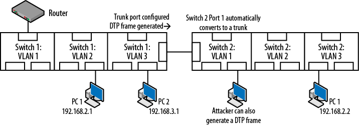
Figure 4-22. Dynamic port configuration security exposure
Initially this auto-configuration sounds convenient but what is to stop an attacker from generating the same message and converting a port in the same way? The attacker’s port will then receive broadcast, multicast and flooded unicast traffic for all VLANs not pruned. In addition to allowing the attacker to learn more about the network, it also means that the attacker may be able to generate tagged frames that will be delivered over the entire network. Whenever possible, dynamic configuration should be turned off.
In addition to pruning for proper VLAN boundaries and the default configurations of the ports, it may be prudent to add a couple of additional configuration changes. Unused ports can be collected into a “deadend VLAN” that is not routed and is pruned from the network. Anyone connecting to a port in this VLAN will be isolated. In addition, many vendors offer security enhancements to ports such as authorized MAC addresses and restricting the number of MAC addresses allowed. When invalid MAC addresses are seen on the port, the port will automatically be shutdown or disabled.
Reading
- IEEE 802.1Q standard is actually entitled “IEEE Standards for Local and Metropolitan Area Networks: Virtual Bridged Local Area Networks”
- ISO/IEC 15802-3 ANSI/IEEE Std 802.1D Information technology—Telecommunications and information exchange between systems—Local and metropolitan area networks—Common specifications—Part 3: Media Access Control (MAC) Bridges
Summary
VLANs are a basic tool for creating network boundaries. While they can create challenges regarding the forwarding of traffic, they can be a powerful tool for handling security and quality of service concerns. This chapter discussed the operation of VLANs and the methods used for propagating VLANs throughout a larger topology. When deploying VLANs and trunks, there are several design considerations to take into account. One must address the basic questions of “Who is talking to whom and why?” As topologies and the VLANs grow, so does the complexity. It is important to review the default operation and configuration of network elements in order to ensure that locally created configurations do not place the network at risk.
Review Questions
Broadcast frames will continue to propagate until they reach a routed interface.
TRUE
FALSE
Broadcast and multicast traffic will cross VLAN boundaries but unicast traffic will not.
TRUE
FALSE
By default, all hosts are connected to the same VLAN.
TRUE
FALSE
Hosts do not usually know to what VLAN they are connected.
TRUE
FALSE
In a contemporary data network, the primary used of a trunk line is to convey VLAN information.
TRUE
FALSE
While they are both part of a switch, the source address table and the VLANs are not integrated in any way.
TRUE
FALSE
Which of the following is the industry standard trunking protocol?
ISL
IEEE 802.1
VLANs
Pruning is the practice of preventing unauthorized access to trunk lines.
TRUE
FALSE
Dynamic port mode is a security risk because by default attackers can see all unpruned VLAN traffic.
TRUE
FALSE
Services such as VoIP and wireless users should be placed in their own VLANs.
TRUE
FALSE
Review Answers
TRUE
FALSE
TRUE
TRUE
TRUE
FALSE
B
FALSE
FALSE
TRUE
Lab Activities
Activity 1—Setting Up a Local VLANs
Materials: A VLAN capable switch and a router. Note: A home gateway may be used if it can be converted to a router to avoid confusion over the NAT operation.
Note: The goal of this particular activity is simply to understand the basic configuration necessary for routing between VLANs without trunks, as shown in Figure 4-23.
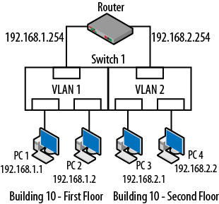
Figure 4-23. Activity 1
On the switch create a pair of VLANs.
Add a host to teach VLAN and determine the IP addressing scheme. As an example one VLAN might use 192.168.1.0 and the other 192.168.2.0. Handy Cisco command:
switchport access vlan X.Connect a router interface to each of the VLANs and assign the proper IP addressing. At this point, the nodes on different networks should be able to successfully PING each other.
Activity 2—VLANs and the SAT
Materials: A VLAN capable switch and a router.
Once the topology from activity 1 is complete, PING between all of the nodes and router interfaces.
On the switch, examine the source address (MAC address) table. Handy Cisco command: show mac-address-table
Compare this table to one in which all of the nodes are in the same VLAN.
Using the information in the SAT and the routing table of the router, develop a step by step procedure for forwarding packets from one computer to the other.
Activity 3—What Can You See?
Materials: A VLAN capable switch, a router and Wireshark.
During this activity, the goal is to determine how far traffic in one VLAN will travel and if it can be seen on another VLAN on the same switch.
Start a capture on one of the network hosts in one of the VLANs.
In the other VLAN, generate broadcast traffic by “PINGing“ an unused IP address on the same network. This will cause an ARP request to be transmitted.
From this same source host, generate unicast traffic by “PINGing” the router.
It turns out that Windows-based computers periodically generate multicast traffic as they search for services.
Did the capture node in the other VLAN see the unicast, multicast or broadcast traffic that was created by the source host? The answer should be “NO.”
As an additional experiment, change the IP address of the capture host so that it is on the same network as the source host. They should now be on the same network but in different VLANs. Attempt to PING between these two nodes. This attempt should fail because even though they are on the same network, the switch has separated them and the traffic is not allowed to cross the VLAN boundary.
Activity 4—Basic Trunking
Materials: A second VLAN capable switch, a trunk capable switch and a router.
Connect another switch to the topology already constructed.
On the new switch create the same VLANs.
Move one host into each VLAN. If you have a shortage of computers, it is sufficient to place one in a VLAN on the first switch and a second in the other VLAN on the new switch, as shown in Figure 4-24.
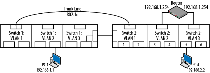
Figure 4-24. Activity 4
On each switch, configure as trunks the ports used to interconnect the two switches. Handy Cisco commands: switchport mode trunk, switchport trunk encapsulation dot1q
At this point, the network hosts should be able to PING each other.
As an additional experiment, explore the capabilities of the switches and attempt to set up a host capable of capturing the traffic running over the trunk. This is typically done with a span, mirror or monitor port. The goal is to examine the IEEE 802.1Q tags used on the trunk. Handy Cisco command: monitor session.
Get Packet Guide to Routing and Switching now with the O’Reilly learning platform.
O’Reilly members experience books, live events, courses curated by job role, and more from O’Reilly and nearly 200 top publishers.

