Mod-el: noun: 1–structural design, 2–a miniature representation, 3–an example for emulation or imitation
Basic network architecture and construction is a good starting point when trying to understand how communication systems function, even though the topic is a bit dull. Architectures are typically based on a model showing how protocols and functions fit together. Historically, there have been many models used for this purpose, including, but not limited to, Systems Network Architecture (SNA-IBM), AppleTalk, Novell Netware (IPX/SPX), and the Open System Interconnection (OSI). Most of these have gone the way of the dodo due to the popularity of TCP/IP. TCP/IP stands for Transmission Control Protocol/Internet Protocol, and represents a suite of protocols used on almost all modern communication systems. As the name suggests, this is the language of the Internet. This chapter focuses on the practical TCP/IP model, using the OSI model as a reference point.
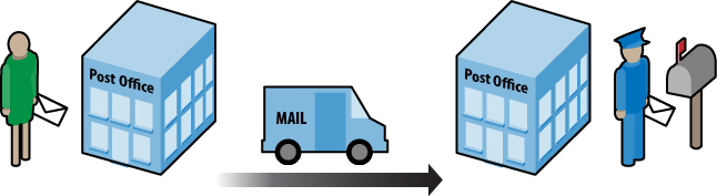
A model is a way to organize a system’s functions and features to define its structural design. A design can help us understand how a communication system accomplishes tasks to form a protocol suite. To help wrap our heads around models, communication systems are often compared to the postal system (Figure 1-1). Imagine writing a letter and taking it to the post office. At some point, the mail is sorted and then delivered via some transport system to another post office. From there, it is sorted and given to a mail carrier for delivery to the destination. The letter is handled at several points along the way. Each part of the system is trying to accomplish the same thing—deliver the mail. But each section has a particular set of rules to obey. While in transit, the truck follows the rules of the road as the letter is delivered to the next point for processing. In between, inspectors and sorters ensure the mail is metered and safe, without much concern for traffic lights or turn signals.
A communication system is not much different, since messages created on a computer are processed and delivered, with each piece of equipment performing some function and obeying certain rules for transmission. Figure 1-2 depicts a typical scenario in which two computers are connected by their network cards via a networking device. Two people are communicating using an application such as instant message or email. At some point we have to decide exactly how to handle this communication. After all, when you mail that letter, you cannot address the envelope in some arbitrary language or ignore zip codes, just as the mail truck driver cannot drive on the wrong side of the road.

So, how is the job of each device or connection determined? An application at the user level should not be responsible for choosing the encoding sequence or the signal type used between the client and server. The letter doesn’t decide to go by air or boat. Similarly, the network interface card (NIC) is not in the business of message header construction, just as the mail sorting system doesn’t care if you use pen or pencil when writing a letter.
Models are routinely organized in a hierarchical or layered structure. Each layer has a set of functions to perform. Protocols are created to handle these functions and, therefore, protocols are also associated with each layer. The protocols are collectively referred to as a protocol suite. The lower layers are often linked with hardware and the upper with software. For example, Ethernet operates at Layers 1 and 2, while the File Transfer Protocol (FTP) operates at the very top of the model. This is true for both the TCP/IP and OSI models. Network traffic can also be viewed in terms of these layers, many of which can actually be seen using a packet capture tool like Wireshark. In Figure 1-3, the major layers of the TCP/IP model are displayed in a message going to a web server.
Before we get too far, let’s do a little reality check. A model describes the entire structure. At the beginning of the chapter, I stated that many of these models “have gone the way of the dodo.” There may have been good ideas in each, but everyone ended up using one model in particular—TCP/IP. For example, both Apple and IBM initially developed their own protocol suites, but converted to TCP/IP due to its popularity. This section explains the historical use of models and provides a more modern viewpoint.
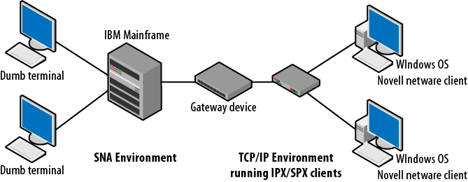
Even a simple communication system is a complicated environment in which thousands or even millions of transactions occur daily. Interconnected systems are considerably more complex. A single electrical disturbance or software configuration error can prevent completion of these transactions. Models provide a starting point for determining what must be done to enable communication or to figure out how systems using different protocols might connect to each other. They also help in troubleshooting problems. For example, how would a Novell Netware client running IPX/SPX communicate with an IBM AS400 over a TCP/IP based network? Figure 1-4 depicts a scenario in which several different platforms might be required to interact with each other. Windows nodes are based on the TCP/IP protocol suite, but, if required, can run Novell Netware client software for network authentication. Novell developed internetworking and transport protocols, called IPX and SPX. At the other end of the network, the IBM mainframe communicates via the protocols used in the SNA model. Imagine the programming and extra effort required to maintain all of the transactions between these separate architectures.
Another example is a network of Apple computers running Appletalk while connecting to a network of Windows machines running TCP/IP.
As I’ve said, TCP/IP is the prevalent architecture today. The complexities of interplatform communication are dramatically reduced with TCP/IP. Protocol systems such as Appletalk, Netware, and SNA are considered legacy. However, understanding protocol layers on a particular communications device or how processes might interact on the network are still critically important ideas. When troubleshooting standard problems or potential security threats, the models and their associated layers offer logical reference points to begin the process. One would not start looking at the routing protocols if the link light was dark.
The OSI model is called a reference model. This means this particular model provides a method by which standards and protocols can be compared in order to assist in connectivity and consistency. Developers can use a reference model to understand how transmissions are framed and create methods to translate between systems.
The OSI basic model is standardized in ISO/IEC (International Standards Organization/International Electrotechnical Commission) 7498, which includes most of the definitions used here. These two organizations have actually created a Joint Technical Committee (JTC) that handles the issues associated with information technology. This model was developed in collaboration with the ITU-T and has also been printed as ITU-T Recommendation X.200. The ITU-T is the International Telecommunications Union—Telecom sector. Now that we’ve had our fill of acronyms, on to the standard.
The first version of ISO/IEC 7498 was written in 1984. This was replaced in 1994 by version 2, with some additional corrections after that date. ISO/IEC 7498 actually has four parts:
| Part 1 – The Basic Model |
| Part 2 – Security Architecture |
| Part 3 – Naming and Addressing |
| Part 4 – Management Framework |
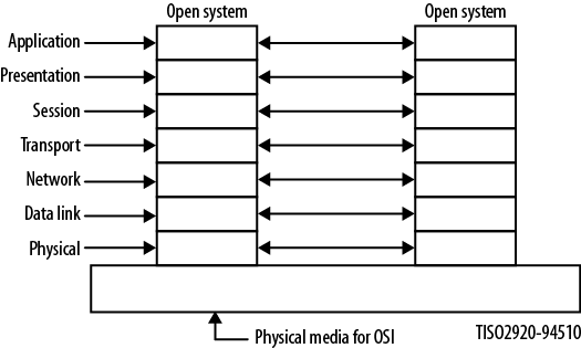
This section examines the basic model, which is defined in section six of 7498-1 as having seven layers: Application, Presentation, Session, Transport, Network, Data Link, and Physical. Figure 1-5 depicts these layers and the connection to a similarly structured open system. An open system is one that adheres to this architecture.
Section 6 of the document also includes the guiding principles for layers, such as:
Not creating so many as to make the engineering of the system difficult
Reducing the number of interactions across a layer boundary
Collecting similar functions and separating fundamentally different functions
Identifying those that may receive a benefit by being based in hardware or software
Additionally, the OSI framework includes as its goals the improvement of current standards, flexibility, and the quality of being “open,” which simply means that systems have mutually adopted accepted standards for the exchange of information. Each of the layers defined in 7498-1 includes specific details about the functions and processes occurring at that layer. It is worth noting that this ISO/IEC/ITU-T document specifically states:
It is not the intent of this reference model to either serve as an implementation specification or to be a basis for appraising the conformance of actual implementations or to provide a sufficient level of detail to define precisely the services and protocols of the interconnection architecture.
So the OSI model does not specify protocols, services, or rules to be used in a communication system, but it does detail the ideas and processes that may be required. Section 7 of 7498-1 provides some particulars for each of the layers, and these are summarized below. If you are driving heavy machinery, be careful in the next section.
- Application
Provides the sole means for the application to access the OSI environment (OSIE) with no layer above it. The functions are divided into connection mode and connectionless mode. Connection mode facilities will include quality of service (QoS), security, identification of the parties, error control, and mode of dialog. Connectionless facilities are essentially a subset of those already mentioned, without error control and some security.
- Presentation
This layer provides for the representation and preservation of the data provided by the Application Layer entities. Specifically, the Presentation Layer is focused on syntax that is acceptable to both ends and access to the layers above and below.
- Session
Specifies both full-duplex and half-duplex modes of operation. This layer provides the means (setup and teardown) for communicating nodes to synchronize and manage the data between them. A mapping is provided between the Transport Layer and Session Layer (session service access point) addresses. Support is present for many-to-one session-to-transport addresses. The bulk of the responsibilities at this layer involve connection-oriented transmissions, but connectionless transmissions are also supported.
- Transport
Protocols at this layer are end-to-end between communicating OSI nodes and deal primarily with low cost and reliable transfer of data. A single Transport Layer address may be associated with many session addresses and provides performance required by each session entity. Basic functions include transport connection establishment, release, data transfer, and QoS. While this layer is not responsible for routing, it does map to Network Layer addressing. All modes handle error control, but when running in connection-oriented mode, sequence control is required.
- Network
Provides the means for managing network connections between open systems. This layer is not responsible for negotiating QoS settings, but rather focuses on routing between networks and subnetworks. Network Layer addresses uniquely identify transport entities. The Network Layer is also responsible for error control, sequencing, and mapping to the data link addresses.
- Data Link
Responsible for the construction of the data link connection between Network Layer entities. The addresses used are unique within the open system set of devices. Like most of the OSI layers, connectionless and connection-oriented modes are utilized. In addition to interfacing with the Network Layer, the data link connection can be built upon one or more Physical Layer interfaces.
- Physical
Like most models, this OSI Physical Layer contains the electrical, mechanical, and functional means to establish physical connections between Layer-2 devices. The interface is largely determined by the medium, but the bit-level transmissions must be organized into their physical service data units.
It is common to limit the discussion of the OSI reference model to the seven layer specifications. While these ideas have been discussed here, the OSI model also provides a potentially valuable insight into the design and implementation of networking models and protocols. The architects of this model spent a lot of time thinking about and enumerating those items demanded at each layer and what is necessary to communicate with the layers immediately above and below. As an example, section five of 7498-1 includes discussion on the various aspects of layering. These include but are not limited to the following:
Communication between peer entities, including the following:
Modes of communication (connection or connectionless)
Relationships between services provided at each adjacent layer boundary
Mode conversion functions (transport and network layers primarily)
Identifiers such as N-address—unambiguous names used to identify a set of service access points at a particular layer
Properties of service access points
Definitions and descriptions of data units
Elements of layer operation
Connections to/from
Multiplexing
Flow control
Segmentation
Sequencing
Acknowledgment
Protocol selection
Negotiation mechanisms
Connection establishment and release
Quality of service
Error detection
Along with these generalized aspects of communication within a layer model, each individual layer adds further discussion where appropriate. For example, the section dedicated to the Transport Layer details connection establishment/release, data transfer, functions within the layer, addressing, multiplexing/splitting, and management. Where necessary (where a one-to-one mapping between services/addresses is not always present), a layer description will include details about the negotiation of the connections between the layers or even sublayers.
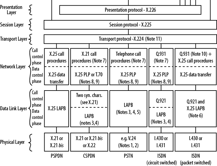
So far we’ve examined a layered model and outlined the responsibilities of each layer. What about the actual protocols? For every protocol used in the TCP/IP model, there is a corresponding (and perhaps more complex) version in the OSI/ITU-T architecture. For ease of access to the reference material, this section refers to the ITU-T X series of standards.
As stated previously, the model itself is described in ITU-T X.200. While the layers are also described, more detailed specifications are contained within X.211-X.217bis. These additional documents are similar to RFCs for individual protocols in that they provide the rules and guidelines for those actually developing protocols, including state diagrams and primitive definitions. For both the Network and Transport Layers, special attention is paid to connectionless- and connection-based communication. One of the major differences between these two forms of transmission is controlling the flow of information between endpoints. It is interesting that the two Layer-4 protocols used today—TCP and UDP (User Datagram Protocol)—are differentiated from each other in the exact same way, with TCP characterized as connection-oriented while UDP is connectionless. TCP is very concerned with sequence numbers and ensuring that all packets arrive at the destination. UDP is not.
Figure 1-6 is from ITU-T X.220 and shows the actual protocols to be used. The original diagram is quite large, so only a portion of it is shown here. While a bit old (written in 1993), it does provide some insight into the structure of the model. Many of the protocols are outdated, but we can see the modularity of the protocol stack that aids in subsystem replacement. For example, at the lower layers, X.25 has been replaced by Frame Relay and ATM. These, in turn, have been replaced by the transmission standards we use today.
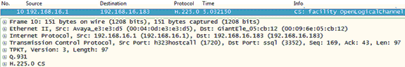
As a practical matter, OSI/ITU-T protocols are not seen nearly as often as the protocols specified for use in the TCP/IP model, although there are exceptions. Some WAN connections continue to use these specifications and, of course, we still have traditional telephony systems. Perhaps one of the best examples of an ITU-T standard that continues to survive even as more and more communications shift to TCP/IP is in the area of VoIP (Voice over IP). H.323, Q.931, and G.711 are still a big part of contemporary VoIP transmissions, as shown in Figure 1-7. H.225 is part of H.323.
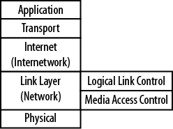
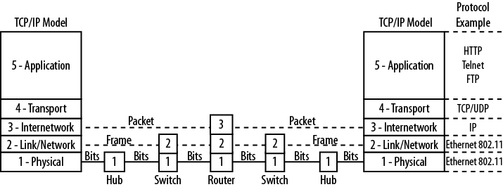
The Internet and almost all networks in use today have standardized on the TCP/IP model. It is often referred to as the language of the Internet, because applications are typically built around this protocol suite. Figure 1-8 shows the TCP/IP model and some of the more well-known protocols and corresponding layers. At Layer 4, there are actually two protocols present—TCP and UDP. While this model shares its name with the former, many operations are based on UDP, so Layer 4 is actually shared by the two protocols. Layers 1 and 2 are governed by the Local Area Network Protocol, but Layer 3 belongs to IP with Internet Control Message Protocol (ICMP) and Internet Group Membership Protocol (IGMP) components of IP-based operations.
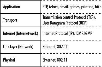
The TCP/IP model does not specify any particular protocol to be run at the lower (LAN) layers. Historically, networks have been built upon many technologies, including fiber distributed data interface (FDDI), Localtalk, Token Ring, Ethernet, and wireless protocols from the 802.11 family of standards. Today, only Ethernet and 802.11 in their various forms survive and even these have eliminated certain variations. For example, Ethernet based on coaxial cable and 802.11 frequency-hopping are almost nonexistent.
In a typical network, most of the decisions regarding protocols, at least for Layers 1–4, are made for you and the real variation is in the applications you chose to deploy. This argument can even be made for advanced technologies such as voice communications, where traditional circuit-switched telephone systems are quickly being replaced by VoIP. The dominance of the TCP/IP model can be demonstrated using a tool within Wireshark. By examining the protocol distribution for a particular network segment, a picture (shown in Figure 1-9) emerges regarding the protocols in use.
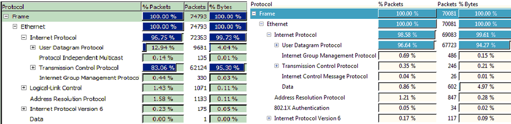
On the left is packet capture data from a Windows machine and on the right from a Mac OS platform. Nearly 100 percent of the Layer-3 traffic caught is IPv4, with a small amount of IPv6. At Layer 4, TCP and UDP dominate, with ARP and 802.1x contributing. Missing from the data collected are protocols from any other model.
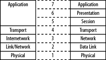
Comparing the TCP/IP and OSI models, it can be said that the functions are the same but the structure is different. Figure 1-10 shows a side-by-side comparison of the OSI and TCP/IP model layers. Layers 5–7 of the OSI model map to Layer 5 of the TCP/IP model.
The TCP/IP model is presented in RFCs 1122 and 1123. These documents, released in 1989, provide the same level of detail encompassed in the ISO/IEC standard. An examination of the standard dates, historical deployments, and the difference in complexity between the two models provides insight into the adoption of TCP/IP over the OSI model. If you survived reading the OSI sections above, you might be left with the impression that the OSI model is very complex in comparison to TCP/IP. A quick look at the “companion” RFCs that go along with RFCs 1122 and 1123 also show a significant level of complexity. To quote from RFC 1122:
This RFC enumerates standard protocols that a host connected to the Internet must use, and it incorporates by reference the RFCs and other documents describing the current specifications for these protocols. It corrects errors in the referenced documents and adds additional discussion and guidance for an implementor.
For each protocol, this document also contains an explicit set of requirements, recommendations, and options. The reader must understand that the list of requirements in this document is incomplete by itself; the complete set of requirements for an Internet host is primarily defined in the standard protocol specification documents, with the corrections, amendments, and supplements contained in this RFC.
As with the OSI model, each layer of the TCP/IP model has a particular set of responsibilities. While most of these are defined in RFC 1122, those for the Application Layer come from RFC 1123. One significant difference between the two models is that RFC 1122 does specify particular protocols at the various layers. What follows are some of the major requirements that must occur at each layer.
- Application
The top TCP/IP layer combines the OSI Application and Presentation Layers and includes user-based and support/management protocols. Items at this layer must do the following:
Support flexibility (naming and length) in hostnames
Map domain names appropriately
Handle DNS errors
Telnet, FTP, Trivial FTP, Simple Mail Transport Protocol, and Domain Name Service all have more specific additional requirements.
- Transport
This layer provides end-to-end communication services based either on TCP (connection-oriented) or UDP (connectionless). TCP is much more concerned with sequence numbers and handshaking than UDP. Items at this layer must do the following:
Pass IP options and Internet Control Message Protocol messages to the Application Layer
Be able to handle and manipulate checksums
Support IP addresses, local and wildcards, such as broadcast, multicast, and unicast destinations
Treat window size as an unsigned number
Manage window size effectively and allow 0 window size
Support urgent data and the pointer that points to last octet of the urgent data
Support TCP options
Gracefully handle opening of connections
Silently discard improper connection requests
Handle retransmissions per recommended algorithms
Follow recommended procedures when generating ACKs (acknowledgments)
Gracefully handle connection failures
- Internet
The Internet Layer specifies the use of IP, ICMP, and Internet Group Management Protocol. Operationally, this is a connectionless “best effort” protocol concerned with addressing, type of service, security, and fragmentation. It relies on upper-layer protocols for accurate delivery. Items in this layer must do the following:
Handle remote multihoming
Meet appropriate gateway specification, if used
Discard improper IP and ICMP packets
Properly handle all forms of addressing including subnets
Maintain packet IDs
Support ToS and reassembly
Support source routing options
- Link Layer
This is the network interface, and includes framing and media access to communicate directly with the network to which it is attached. Items at this layer must:
Clear the ARP cache
Prevent ARP floods
Send and receive RFC 894 encapsulation (should also support IEEE 802)
Use ARP on Ethernet and IEEE 802 networks
Report link layer broadcasts to Internetwork Layer.
Receive IP ToS values
- Physical
Typically, the network interface card or port defines the Physical Layer. Each LAN protocol has within its specification the electrical and mechanical characteristics for communication on the link. These include items such as voltage level, encoding, pin assignments, and shape of the interface.
Not all of the requirements were actually implemented in protocol suites running on hosts and network equipment. For example, IP hosts were intended to be much more active in detecting gateway or next hop failures. The reality is that if a gateway fails, hosts simply can’t communicate to destinations outside their networks.
The models discussed in this chapter are usually drawn from the top layer (application) down. Wireshark displays them in reverse order, as shown in Figure 1-11, where the protocols corresponding to Layers 1–5 are identified. This packet happens to be from a VoIP conversation. Starting from the bottom of the model, we see Ethernet Type II (also called Ethernet Type 2 or Ethernet II). Ethernet as a protocol exists at Layers 1 and 2, with Layer 2 defining the frame (error control, addressing, etc.) and the Ethernet network interface defining the Physical Layer characteristics.

In addition, Layer 2 LAN protocols can be split into two major areas: logical link control (LLC) and media access control (MAC). These become sublayers within the model. LLC functions include frame construction, error control, and addressing. The MAC layer defines line discipline and network transmission. Specifically, this includes a method for determining which node is in line to communicate and for how long. Figure 1-12 depicts these TCP/IP sublayers. Sublayers are also found in the OSI model.
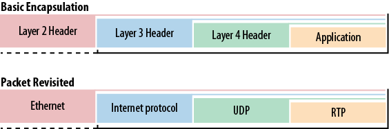
Encapsulation is the method by which the various layers interact and pass information up and down the protocol stack. A message generated by an application must be formatted for transmission. On the sending node, the upper layer places packaging around the message that describes the application used to generate the message. This is called the header. The package and header are then passed to the next layer down. Each layer completes its own required encapsulation operation that includes a header.
By the time the message reaches the bottom of the protocol stack, it has several of these wrappers. This process is the encapsulation. For ease of processing, each header contains information regarding the contents. Thus, the Ethernet header provides some indication that it has encapsulated IP. The IP header indicates that it was carrying TCP, and so on. Basic encapsulation and the encapsulation specific to the packet in Figure 1-11 are shown in Figure 1-13.
At the receiving node, the same process occurs, but in reverse. Each layer, beginning with the lowest, processes the appropriate information and strips off the outermost wrapper before handing the message to the next layer up. This continues as the message travels up the stack until the last bit of packaging is removed. This process is called de-encapsulation.
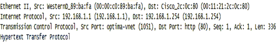
The packet shown in Figure 1-14 has been expanded to reveal the headers. Each layer contains a code indentifying the content of the encapsulated data. Ethernet uses the code 0800 to indicate that IP is encapsulated. At Layer 3, IP uses code 17 to show that it has encapsulated UDP. At Layer 4, UDP uses port numbers to direct the data to the proper process or application. The receiver uses this information to properly parse and de-encapsulate the data.
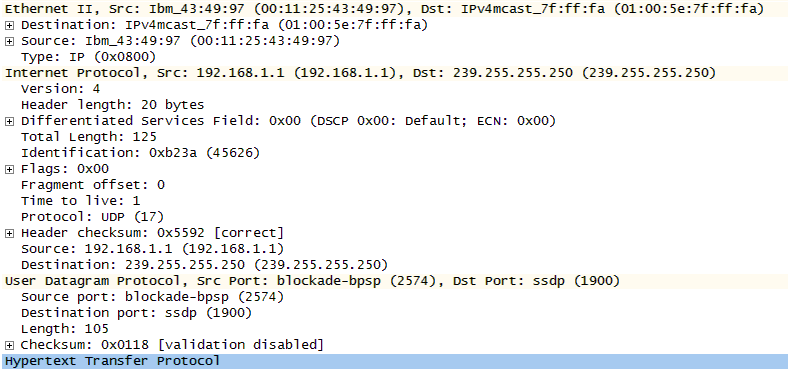
Addressing used within networked systems can also be tied to layers and equipment, as shown in Figure 1-14. Some protocols require addressing as part of their basic operation. For example, an Ethernet switch processes Layer-2 frames, which contain addresses called hardware or MAC addresses. For example, the source MAC address in Figure 1-14 is 00:11:25:43:49:97. The Internet Protocol uses IP addresses at Layer 3, and these are processed by routers. In this case, the source is 192.168.1.1 and the destination is 239.255.255.250. Both TCP and UDP communicate via port numbers at Layer 4. Thus, a TCP/UDP message not only possesses the port numbers necessary to communicate with an application, but also the IP and MAC addresses necessary to complete the transmission. Understanding relationships like these better prepares the network administrator to build, troubleshoot, or secure the infrastructure. For example, if the administrator is concerned about port scanning at Layer 4, it is unlikely that solutions will be found by working with the network switches down at Layer 2.
Layering the model can also provide a picture of device responsibilities. Each device on a network is designed for a particular task. They have different levels of intelligence and process traffic in a variety of ways. By applying the layers to equipment, the impact on traffic and capabilities of the device at that particular location are easier to understand. Routers and switches form the building blocks of almost any network. While they have many individual features and can be configured for a variety of functions, they all provide the same basic services when you plug them, regardless of the vendor. The relationship between devices, addressing, and the layers is outlined in Figure 1-15.
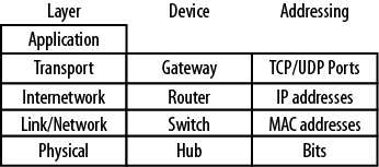
Switches operate at Layer 2 and forward LAN frames based upon the MAC addresses contained within those frames. They also perform error checking for each frame. Switches also provide some measure of network segmentation, since the processing of MAC addresses will result in network traffic control. Switches have a variety of management features such as support for Simple Network Management Protocol (SNMP) and virtual local area networks (VLANs).
Routers operate at Layer 3 and process IP packets. They will read Layer-2 frames when their MAC addresses appear in the frames, but their main function is to get IP packets to the proper destination. In so doing, the router calculates the IP header checksum and can act on any QoS or fragmentation information the packet contains. Many routers also support advanced features such as firewalling, virtual private networks (VPNs) termination, authentication, and network address translation (NAT).
The term gateway has several meanings. Routers and network hosts are configured with a default gateway, but this is actually a router. It is called a default gateway because this is the network path to the rest of the world. The more traditional gateway existing at Layer 4 is a device used to convert between systems that do not share the same networking model. This type of environment is depicted in Figure 1-4, and requires protocol translation for network nodes to communicate. We might say this sort of thing is another legacy item, but with the emergence of VoIP, the gateway is making a comeback. The language of the public switched telephone network (PSTN) is Signaling System 7 (SS7). A gateway that understands both TCP/IP and SS7 is required if an IP-based VoIP phone is to communicate with a traditional telephone.
Not all devices fit neatly into boxes. An access point is sometimes referred to as a wireless hub because it broadcasts certain kinds of traffic everywhere. However, like an Ethernet switch, the access point is not only aware of MAC addresses, it uses them to make some forwarding decisions. More recently, the emergence of multilayer switching has blurred the line between processing frames at Layer 2 and some of the higher level functions like routing. Figure 1-16 provides an example of how these devices and addresses interact within the confines of the protocol layers.
ISO/IEC 7498-1: “Information Technology — Open Systems Interconnection — Basic Reference Model: The Basic Model” (Joint Technical Committee)
ITU-T X.200: “Information Technology — Open Systems Interconnection — Basic Reference Model: The Basic Model” (International Telecommunication Union)
ITU-T X.220: Open Systems Interconnection — General Connection Mode Protocol Specifications “Use of X200-Series Protocols in CCITT Applications —” (International Telecommunication Union)
RFC 1122: “Requirements for Internet Hosts — Communication Layers” (Internet Engineering Task Force)
RFC 1123: “Requirements for Internet Hosts — Application and Support” (Internet Engineering Task Force)
The OSI and TCP/IP models provide an architecture in which the functions and rules for communication, addressing, and equipment are organized. The OSI model is standardized in ITU-T X.200, and the companion documents X.211-X.217 and X.220 provide the specifications for the developers and protocols. The TCP/IP model is described in RFC 1122, which lists the required protocols for hosts that communicate on the network.
The OSI model, now primarily considered a reference model, is in limited use. The TCP/IP model is the language of the Internet. Adoption of IP-based communication in many systems such as VoIP will further marginalize the OSI model’s use, a factor not lost on major companies like Apple and Novell, who have adopted the TCP/IP model.
Modern practitioners and researchers will be well served by an understanding of standards for communication requirements in widely varying conditions. These architectures help us to better understand the evolution of communication standards.
What is the name of the process by which an upper-layer protocol is wrapped up in a lower-layer protocol?
Name four communication models.
What two documents specify the standardization of the OSI model?
How many layers are in the OSI and TCP/IP models, respectively?
Name the layers of the OSI model.
Name the layers of the TCP/IP model.
What two documents present and detail the use of the TCP/IP model?
There are two forms of communication described in both standards. These forms are predominantly part of Layers 3 and 4. What are they?
Network administrators typically have the ability to use whatever protocols they wish, regardless of the layer in question. True or False?
One big difference between the documentation of the TCP/IP and OSI standards is that the TCP/IP RFC specifies the protocols to be used and the OSI ITU-T model documentation does not. True or False?
For each address type or device, specify its proper layer (Layer 2, Layer 3, or Layer 4).
Switch
Router
Gateway
MAC address
IP address
Port number
Encapsulation
TCP/IP, OSI, SNA, Appletalk, Novell (IPX/SPX)
ISO/IEC 7498 and ITU-T X.200
7, 5
Application, Presentation, Session, Transport, Network, Data Link, Physical
Application, Transport, Internet, Data Link, Physical
RFCs 1122 and 1123
Connection-mode (oriented) and connectionless-mode
False
True
Layer 2, Layer 3, Layer 4, Layer 2, Layer 3, Layer 4
Materials: Wireshark and a network connection
Start a capture.
Complete several different transactions from your computer.
Stop the capture and examine the individual packets.
Find examples of the following: ARP, ICMP, TCP, UDP, and IPv6.
Describe these packets in terms of their encapsulation or protocol stacks.
Materials: Wireshark and a network connection
Start a capture and allow it to run for several minutes, the longer the better.
Complete as many different transactions from your computer as possible.
From the Statistics menu in Wireshark, select Protocol Hierarchy.
Examine the distribution or protocols and attempt to determine the models used and the level of traffic specific to each protocol. What is the most common upper-layer protocol? What caused it to be generated?
Using the models discussed in this chapter as references, develop a series of rules or parameters that describe a conversation between two people who have never met. Things to consider might include the mode of communication, language, nonverbal communication, access method, body language, expressions, speed, and parameter negotiation.
Get Packet Guide to Core Network Protocols now with the O’Reilly learning platform.
O’Reilly members experience books, live events, courses curated by job role, and more from O’Reilly and nearly 200 top publishers.

