IQ Imbalance
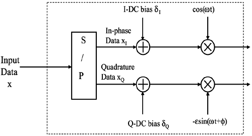
The final RF subsystem discussed in this chapter is the in-phase and quadrature (IQ) modulator shown in Figure 5.1. A functional block diagram of a real IQ modulator is shown in Figure 5.32.
Figure 5.32. A block diagram of a real IQ modulator.

The figure shows the DC offset that can occur on either the I or Q branch. Ideally, these values are zero. Also, the amplitude and phase imbalances are denoted by ∊ and φ, respectively. Let's examine the effects of these imbalance. Given an input data sequence x. The ideal complex modulate carrier waveform y(t) is
Equation 5.54
while the IQ imbalanced modulated waveform is
Equation 5.55
Get OFDM Wireless LANs: A Theoretical and Practical Guide now with the O’Reilly learning platform.
O’Reilly members experience books, live events, courses curated by job role, and more from O’Reilly and nearly 200 top publishers.

