2.3. APPLICATION SCENARIOS
[RFC2702] lays out the requirements for traffic engineering with MPLS by listing the desirable properties of a TE solution. Rather than discussing the requirements in abstract terms, the following section illustrates them by looking at three application scenarios. At the end of this section we discuss why MPLS is a powerful tool for satisfying these requirements.
Figure 2.1. A network with two sources, A and B, and two unequal cost paths to destination D
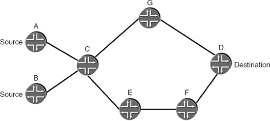
The network topology used in all scenarios is shown in Figure 2.1.
Two sources, A and B, send traffic to destination D through node C. The cost of a path is measured in terms of the link metrics. When all metrics are equal, the cost simply translates to the number of hops in the path. In the sample network, two unequal cost paths exist between C and D. All links are of the same capacity and speed, unless specified otherwise.
The first application scenario highlights the need to forward traffic along a predefined path. In the example network in Figure 2.1, assume that A and B are two customers and that customer A buys a service that guarantees low latency. Assume that the link G–D is a satellite link. From the operator's point of view, the requirement is that traffic originating at A should avoid the high-latency link G–D. Thus, a path must be found from A to D that avoids the link G–D. In the simple ...
Get MPLS-Enabled Applications: Emerging Developments and New Technologies now with the O’Reilly learning platform.
O’Reilly members experience books, live events, courses curated by job role, and more from O’Reilly and nearly 200 top publishers.

