6.15. ROOT LOCUS OF TIME-DELAY FACTORS [26–28]
We previously considered time-delay factors in Section 6.7 when we discussed the Bode-diagram approach. The transfer function of a time-delay factor was defined in Eq. (6.95), and an example was solved using the Bode-diagram approach for a unity feedback control system whose forward transfer function was defined in Eq. (6.103). How would we draw the root locus of a control system containing a time-delay factor?
To answer this question, let us consider a unity-feedback control system whose forward transfer function, which contains a time-delay factor, is given by the following
![]()
and is illustrated in Figure 6.63.
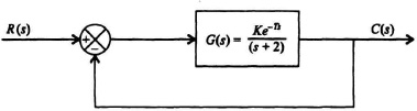
Figure 6.63 Control system containing a time-delay factor.
The characteristic equation of the control system shown in Figure 6.63 is given by
![]()
or
![]()
Therefore, the angular condition is given by
![]()
The angular condition of e−Ts is given by
Since the term e−Tσ is real, its angular value is zero. Therefore,
as shown in Eq. (6.96). Therefore, ...
Get Modern Control System Theory and Design, 2nd Edition now with the O’Reilly learning platform.
O’Reilly members experience books, live events, courses curated by job role, and more from O’Reilly and nearly 200 top publishers.

