Chapter 9
Reduced-Complexity Sphere Detection for Uncoded SDMA-OFDM Systems
9.1 Introduction
9.1.1 System Model
Figure 9.1 shows an SDMA/OFDM Uplink (UL) transmission scenario, where each of the U users is equipped with a single transmit antenna, while the BS has N receive antenna elements. Based on our rudimentary discourse on MIMO-OFDM in Section 1.1.1, for each subcarrier the link between each pair of transmit and receiver antennas may be characterized with the aid of a unique user-specific FDCTF denoted as hnu in Figure 9.1. The subscripts of h, i.e. u and n, represent the user and receive antenna element index at the BS, respectively. For example, the FD-CTF or the spatial signature of the uth user can be expressed as a column vector:
Figure 9.1: Schematic of an SDMA uplink MIMO channel scenario. 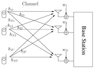
with u Є 1,… U. If the transmitted signal of the uth user is denoted by su and the received signal plus the Additive White Gaussian Noise (AWGN) at the nth receive antenna element is represented by yn and wn, respectively, the entire SDMA/OFDM system can be described on a per-subcarrier basis by a matrix equation written as
where the received signal’s column vector is

