APPENDIX F
PENTIUM INSTRUCTION FORMAT AND TIMING
Table F-2, Table F-3, and Table F-5 list all instructions along with instruction encoding diagrams and clock counts.
F.1. INTEGER INSTRUCTION FORMAT AND TIMING
The following sections explain how to use each of the columns of Table F-2.
Format
All instruction encodings are subsets of the general instruction format shown in Figure F-1. Instructions consist of one or two primary opcode bytes, possibly an address specifier consisting of the mod r/m byte and scale-index-base byte, a displacement if required, and an immediate data field if required.
Within the primary opcode or opcodes, smaller encoding fields may be defined. These fields vary according to the class of operation. The fields define such information as direction of the operation, size of displacements, register encoding, or sign extension.
Almost all instructions referring to an operand in memory have an addressing mode byte following the primary opcode byte(s). This byte, the mod r/m byte, specifies the address mode to be used. Certain encodings of the mod r/m byte indicate that a second addressing byte, the scale-index-base byte, follows the mod r/m byte to fully specify the addressing mode.
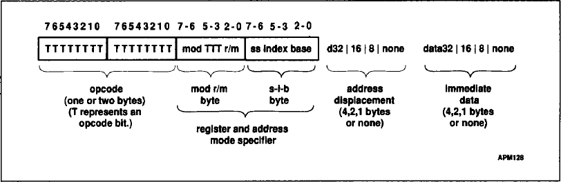
Figure F-1. General Instruction Format
Addressing modes can include a displacement immediately following the mod r/m byte or scale-index-base byte. If a displacement is present, the ...
Get Microprocessor Theory and Applications with 68000/68020 and Pentium now with the O’Reilly learning platform.
O’Reilly members experience books, live events, courses curated by job role, and more from O’Reilly and nearly 200 top publishers.

