Where the analog input pins are designed to read analog sensors (input), the PWM pins are designed for output. PWM is a technique for obtaining analog results with digital output.
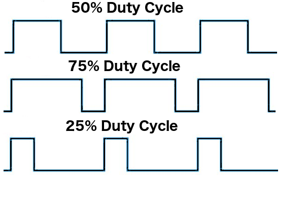
Since a digital output can be either on or off, to obtain the analog output the digital output is switch between HIGH and LOW rapidly. The percentage of the time that the signal is high is called the duty cycle. The following diagram illustrates this concept:
We have the ability to set the frequency of how fast the signal can switch between HIGH and LOW. This frequency is measured in Hertz and sets how many times the signal can switch per second. For example, ...

