The following diagram shows the Fritzing diagram for this project:
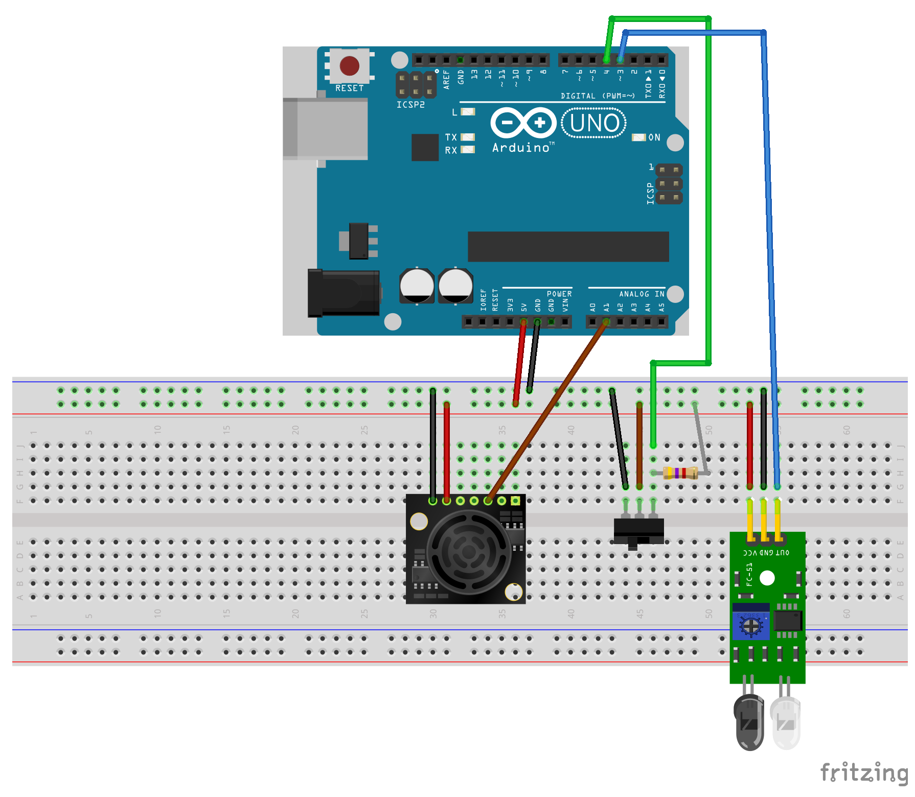
The middle sensor, shown in the diagram, represents the crash sensor because there isn't a Fritzing part for a crash sensor. The switch in the diagram has the same pin layout as the crash sensor shown earlier in this chapter.
In the diagram, we can see that all of the ground pins on the sensors are connected to the ground rail of the breadboard and all of the VCC pins on the sensors are connected to the power rail on the breadboard.
The analog out on the EZ1 Ultrasonic sonar sensor is connected to the A1 analog pin on the Arduino, the crash sensor is connected ...

