The following diagram shows the Fritzing diagram for this project:
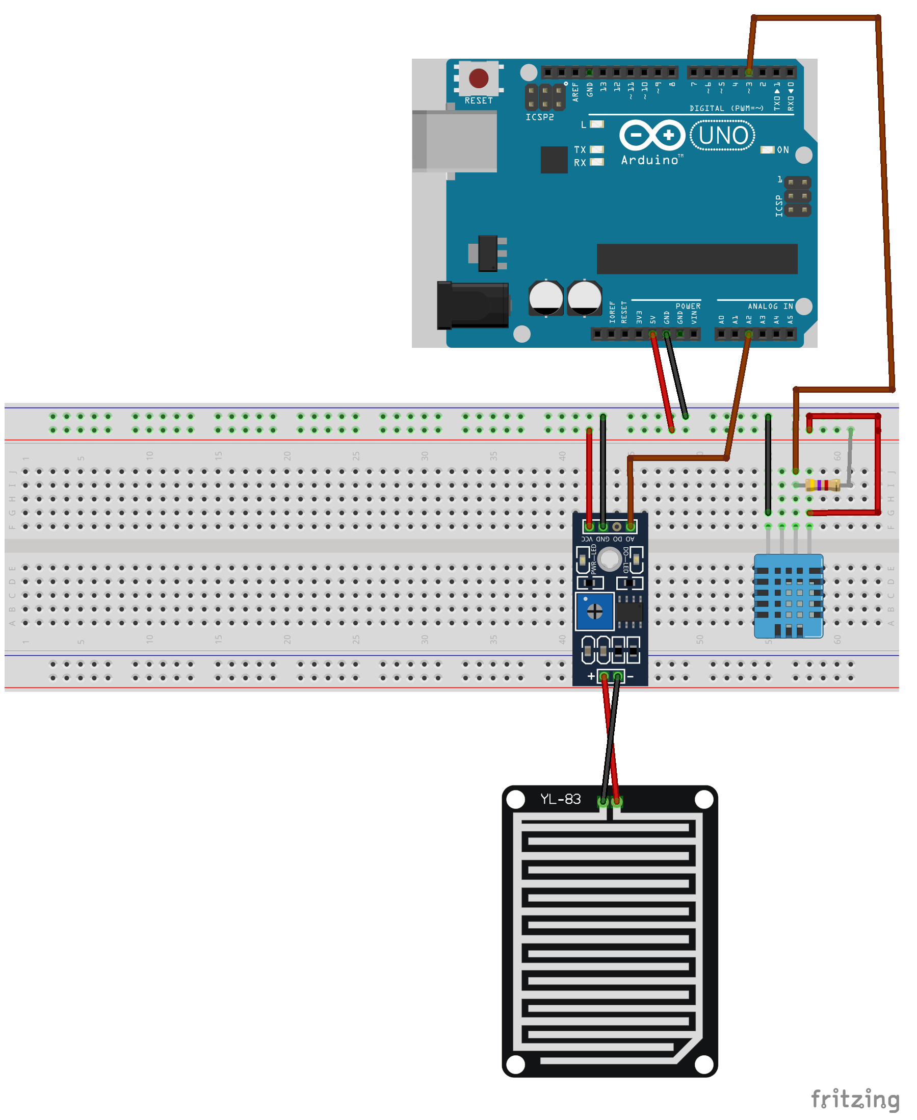
In this diagram, we can see that the VCC and ground pins on both sensors are connected to the power and ground rails on the breadboard. The power and ground rails on the breadboard are connected to the 5V out and the ground pins on the Arduino.
The image of the DHT11 sensor that we showed earlier in this chapter shows a DHT11 sensor with three pins; however, the sensor in the Fritzing library has four pins. It is safe to ignore the extra pin on the Fritzing diagram.
This diagram shows that the data pin on the DHT11 sensor is connected to the digital 3 pin on ...

