The following diagram shows the Fritzing diagram for this project:
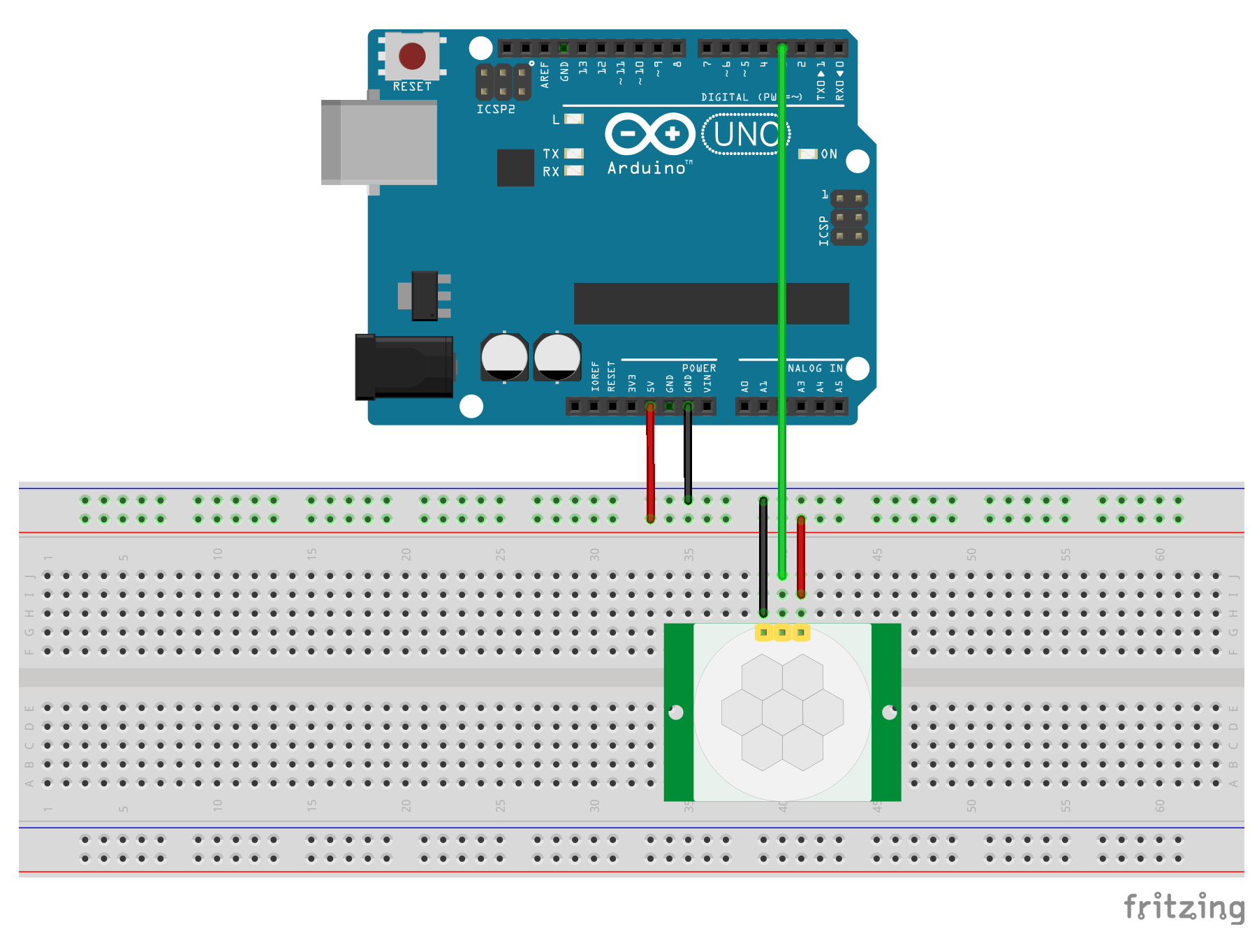
With the diagram, we can see that the ground pin on the HC-SR501 motion sensor is connected to the ground rail on the breadboard and the 5V input on the motion sensor is connected to the power rail on the breadboard. The power and ground rails of the breadboard are connected to the 5V power and ground pins on the Arduino.
The output pin on the motion sensor is a digital output (either HIGH or LOW), therefore we can connect the output pin directly to any of the digital pins on the Arduino. In this case, we are connecting the output pin from the sensor to pin ...

