Chapter 5
RF Channel Analysis
This chapter describes the signal to be transmitted and its interaction with the RF channel where it propagates. The material contained here presents aspects relevant to an RF network designer to allow him to properly perform his tasks. This book assumes that the reader is familiar with the subject; otherwise we suggest reading Chapter 9 of my book, Designing cdma2000 Systems published by Wiley in 2004.
5.1 The Signal
Digital wireless communications transmit digital information (sets of 1 and 0s) by changing the amplitude and phase of a carrier (phase modulation). This phase shift is done by combining two sinusoids shifted by 90°, as explained in Chapter 4. Amplitude variation of those sinusoids allows for the generation of sinusoids with different amplitude and phase shifts. This is called quadrature phase modulation or quadrature amplitude modulation (which also includes phase). Quadrature stands for the two sinusoids shifted by 90°.
To calculate the spectrum of each symbol transition in phase modulation, we can consider a continuous sine wave multiplied by a rectangular pulse that has one symbol width, as shown in Figures 5.1 and 5.2.
Figure 5.1 Carrier sine wave and symbol pulse.
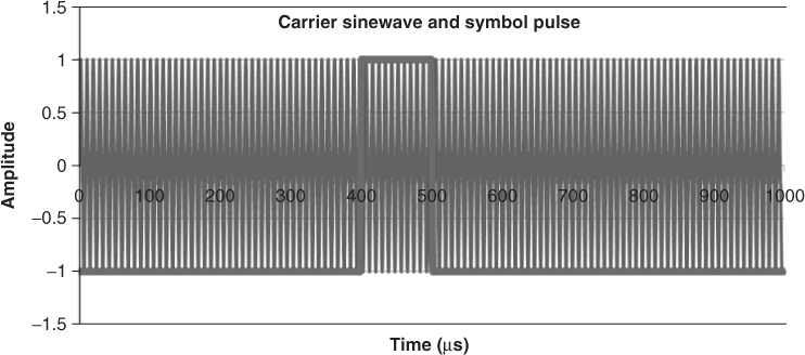
Figure 5.2 Carrier symbol-carrier sine wave multiplied by symbol pulse.
The spectrum of a phase-modulated signal results from the convolution of a sine wave with ...

