Whereas Chapter 8 introduced the lowest levels of hardware control, this chapter provides an overview of the higher-level bus architectures. A bus is made up of both an electrical interface and a programming interface. In this chapter, we deal with the programming interface.
This chapter covers a number of bus architectures. However, the primary focus is on the kernel functions that access PCI peripherals, because these days the PCI bus is the most commonly used peripheral bus on desktops and bigger computers, and the one that is best supported by the kernel. ISA is still common for electronic hobbyists and is described later, although it is pretty much a bare-metal kind of bus and there isn’t much to say in addition to what is covered in Chapter 8 and Chapter 9.
Although many computer users think of PCI (Peripheral Component Interconnect) as a way of laying out electrical wires, it is actually a complete set of specifications defining how different parts of a computer should interact.
The PCI specification covers most issues related to computer interfaces. We are not going to cover it all here; in this section we are mainly concerned with how a PCI driver can find its hardware and gain access to it. The probing techniques discussed in Section 2.6 in Chapter 2, and Section 9.3.2 in Chapter 9 can be used with PCI devices, but the specification offers a preferable alternative to probing.
The PCI architecture was designed as a replacement for the ISA standard, with three main goals: to get better performance when transferring data between the computer and its peripherals, to be as platform independent as possible, and to simplify adding and removing peripherals to the system.
The PCI bus achieves better performance by using a higher clock rate than ISA; its clock runs at 25 or 33 MHz (its actual rate being a factor of the system clock), and 66-MHz and even 133-MHz implementations have recently been deployed as well. Moreover, it is equipped with a 32-bit data bus, and a 64-bit extension has been included in the specification (although only 64-bit platforms implement it). Platform independence is often a goal in the design of a computer bus, and it’s an especially important feature of PCI because the PC world has always been dominated by processor-specific interface standards. PCI is currently used extensively on IA-32, Alpha, PowerPC, SPARC64, and IA-64 systems, and some other platforms as well.
What is most relevant to the driver writer, however, is the support for autodetection of interface boards. PCI devices are jumperless (unlike most older peripherals) and are automatically configured at boot time. The device driver, then, must be able to access configuration information in the device in order to complete initialization. This happens without the need to perform any probing.
Each PCI peripheral is identified by a bus
number, a device number, and a
function number. The PCI specification permits
a system to host up to 256 buses. Each bus hosts up to 32 devices,
and each device can be a multifunction board (such as an audio device
with an accompanying CD-ROM drive) with a maximum of eight functions.
Each function can thus be identified at hardware level by a 16-bit
address, or key. Device drivers written for Linux, though, don’t need
to deal with those binary addresses as they use a specific data
structure, called pci_dev, to act on the devices.
(We have already seen struct pci_dev, of course, in
Chapter 13.)
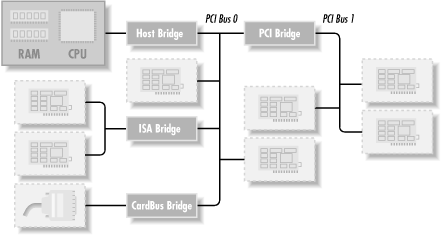
Most recent workstations feature at least two PCI buses. Plugging more than one bus in a single system is accomplished by means of bridges, special-purpose PCI peripherals whose task is joining two buses. The overall layout of a PCI system is organized as a tree, where each bus is connected to an upper-layer bus up to bus 0. The CardBus PC-card system is also connected to the PCI system via bridges. A typical PCI system is represented in Figure 15-1, where the various bridges are highlighted.
The 16-bit hardware addresses associated with PCI peripherals,
although mostly hidden in the struct pci_dev
object, are still visible occasionally, especially when lists of
devices are being used. One such situation is the output of
lspci (part of the
pciutils package, available with most
distributions) and the layout of information in
/proc/pci and
/proc/bus/pci.[55] When the hardware address is displayed, it
can either be shown as a 16-bit value, as two values (an 8-bit bus
number and an 8-bit device and function number), or as three values
(bus, device, and function); all the values are usually displayed in
hexadecimal.
For example, /proc/bus/pci/devices uses a single
16-bit field (to ease parsing and sorting), while
/proc/bus/
busnumber
splits the address into three fields. The following shows how those
addresses appear, showing only the beginning of the output lines:
rudo%lspci | cut -d: -f1-200:00.0 Host bridge 00:01.0 PCI bridge 00:07.0 ISA bridge 00:07.1 IDE interface 00:07.3 Bridge 00:07.4 USB Controller 00:09.0 SCSI storage controller 00:0b.0 Multimedia video controller 01:05.0 VGA compatible controller rudo%cat /proc/bus/pci/devices | cut -d\ -f1,30000 0 0008 0 0038 0 0039 0 003b 0 003c b 0048 a 0058 b 0128 a
The two lists of devices are sorted in the same order, since
lspci uses the /proc
files as its source of information. Taking the VGA video controller as
an example, 0x128 means 01:05.0 when split into bus
(eight bits), device (five bits) and function (three bits). The second field in
the two listings shown shows the class of device and the interrupt
number, respectively.
The hardware circuitry of each peripheral board answers queries pertaining to three address spaces: memory locations, I/O ports, and configuration registers. The first two address spaces are shared by all the devices on a PCI bus (i.e., when you access a memory location, all the devices see the bus cycle at the same time). The configuration space, on the other hand, exploits geographical addressing. Configuration transactions (i.e., bus accesses that insist on the configuration space) address only one slot at a time. Thus, there are no collisions at all with configuration access.
As far as the driver is concerned, memory and I/O regions are accessed in the usual ways via inb, readb, and so forth. Configuration transactions, on the other hand, are performed by calling specific kernel functions to access configuration registers. With regard to interrupts, every PCI slot has four interrupt pins, and each device function can use one of them without being concerned about how those pins are routed to the CPU. Such routing is the responsibility of the computer platform and is implemented outside of the PCI bus. Since the PCI specification requires interrupt lines to be shareable, even a processor with a limited number of IRQ lines, like the x86, can host many PCI interface boards (each with four interrupt pins).
The I/O space in a PCI bus uses a 32-bit address bus (leading to 4 GB of I/O ports), while the memory space can be accessed with either 32-bit or 64-bit addresses. However, 64-bit addresses are available only on a few platforms. Addresses are supposed to be unique to one device, but software may erroneously configure two devices to the same address, making it impossible to access either one; the problem never occurs unless a driver is willingly playing with registers it shouldn’t touch. The good news is that every memory and I/O address region offered by the interface board can be remapped by means of configuration transactions. That is, the firmware initializes PCI hardware at system boot, mapping each region to a different address to avoid collisions.[56] The addresses to which these regions are currently mapped can be read from the configuration space, so the Linux driver can access its devices without probing. After reading the configuration registers the driver can safely access its hardware.
The PCI configuration space consists of 256 bytes for each device function, and the layout of the configuration registers is standardized. Four bytes of the configuration space hold a unique function ID, so the driver can identify its device by looking for the specific ID for that peripheral.[57] In summary, each device board is geographically addressed to retrieve its configuration registers; the information in those registers can then be used to perform normal I/O access, without the need for further geographic addressing.
It should be clear from this description that the main innovation of the PCI interface standard over ISA is the configuration address space. Therefore, in addition to the usual driver code, a PCI driver needs the ability to access configuration space, in order to save itself from risky probing tasks.
For the remainder of this chapter, we’ll use the word
device to refer to a device function, because
each function in a multifunction board acts as an independent
entity. When we refer to a device, we mean the tuple “bus number,
device number, function number,” which can be represented by a 16-bit
number or two 8-bit numbers (usually called bus and
devfn).
To see how PCI works, we’ll start from system boot, since that’s when the devices are configured.
When power is applied to a PCI device, the hardware remains inactive. In other words, the device will respond only to configuration transactions. At power on, the device has no memory and no I/O ports mapped in the computer’s address space; every other device-specific feature, such as interrupt reporting, is disabled as well.
Fortunately, every PCI motherboard is equipped with PCI-aware firmware, called the BIOS, NVRAM, or PROM, depending on the platform. The firmware offers access to the device configuration address space by reading and writing registers in the PCI controller.
At system boot, the firmware (or the Linux kernel, if so configured) performs configuration transactions with every PCI peripheral in order to allocate a safe place for any address region it offers. By the time a device driver accesses the device, its memory and I/O regions have already been mapped into the processor’s address space. The driver can change this default assignment, but it will never need to do that.
As suggested, the user can look at the PCI device list and the devices’
configuration registers by reading
/proc/bus/pci/devices and
/proc/bus/pci/*/*. The former is a text file with
(hexadecimal) device information, and the latter are binary files that
report a snapshot of the configuration registers of each device, one
file per device.
As mentioned earlier, the layout of the configuration space is device independent. In this section, we look at the configuration registers that are used to identify the peripherals.
PCI devices feature a 256-byte address space. The first 64 bytes are standardized, while the rest are device dependent. Figure 15-2 shows the layout of the device-independent configuration space.
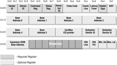
As the figure shows, some of the PCI configuration registers are required and some are optional. Every PCI device must contain meaningful values in the required registers, whereas the contents of the optional registers depend on the actual capabilities of the peripheral. The optional fields are not used unless the contents of the required fields indicate that they are valid. Thus, the required fields assert the board’s capabilities, including whether the other fields are usable or not.
It’s interesting to note that the PCI registers are always
little-endian. Although the standard is designed to be architecture
independent, the PCI designers sometimes show a slight bias toward the
PC environment. The driver writer should be careful about byte
ordering when accessing multibyte configuration registers; code that
works on the PC might not work on other platforms. The Linux
developers have taken care of the byte-ordering problem (see Section 15.1.4), but the issue must be kept
in mind. If you ever need to convert data from host order to PCI order
or vice versa, you can resort to the functions defined in
<asm/byteorder.h>, introduced in Chapter 10, knowing that PCI byte order is little-endian.
Describing all the configuration items is beyond the scope of this book. Usually, the technical documentation released with each device describes the supported registers. What we’re interested in is how a driver can look for its device and how it can access the device’s configuration space.
Three or five PCI registers identify a device:
vendorID, deviceID, and
class are the three that are always used. Every
PCI manufacturer assigns proper values to these read-only registers,
and the driver can use them to look for the device. Additionally, the
fields subsystem vendorID and subsystem deviceID are sometimes set by the vendor to further
differentiate similar devices.
Let’s look at these registers in more detail.
-
vendorID This 16-bit register identifies a hardware manufacturer. For instance, every Intel device is marked with the same vendor number,
0x8086. There is a global registry of such numbers, maintained by the PCI Special Interest Group, and manufacturers must apply to have a unique number assigned to them.-
deviceID This is another 16-bit register, selected by the manufacturer; no official registration is required for the device ID. This ID is usually paired with the vendor ID to make a unique 32-bit identifier for a hardware device. We’ll use the word signature to refer to the vendor and device ID pair. A device driver usually relies on the signature to identify its device; you can find what value to look for in the hardware manual for the target device.
-
class Every peripheral device belongs to a class. The
classregister is a 16-bit value whose top 8 bits identify the “base class” (or group). For example, “ethernet” and “token ring” are two classes belonging to the “network” group, while the “serial” and “parallel” classes belong to the “communication” group. Some drivers can support several similar devices, each of them featuring a different signature but all belonging to the same class; these drivers can rely on theclassregister to identify their peripherals, as shown later.-
subsystem vendorID,subsystem deviceID These fields can be used for further identification of a device. If the chip in itself is a generic interface chip to a local (onboard) bus, it is often used in several completely different roles, and the driver must identify the actual device it is talking with. The subsystem identifiers are used to this aim.
Using those identifiers, you can detect and get hold of your device. With version 2.4 of the kernel, the concept of a PCI driver and a specialized initialization interface have been introduced. While that interface is the preferred one for new drivers, it is not available for older kernel versions. As an alternative to the PCI driver interface, the following headers, macros, and functions can be used by a PCI module to look for its hardware device. We chose to introduce this backward-compatible interface first because it is portable to all kernel versions we cover in this book. Moreover, it is somewhat more immediate by virtue of being less abstracted from direct hardware management.
-
#include <linux/config.h> The driver needs to know if the PCI functions are available in the kernel. By including this header, the driver gains access to the
CONFIG_macros, includingCONFIG_PCI, described next. But note that every source file that includes<linux/module.h>already includes this one as well.-
CONFIG_PCI This macro is defined if the kernel includes support for PCI calls. Not every computer includes a PCI bus, so the kernel developers chose to make PCI support a compile-time option to save memory when running Linux on non-PCI computers. If
CONFIG_PCIis not enabled, every PCI function call is defined to return a failure status, so the driver may or may not use a preprocessor conditional to mask out PCI support. If the driver can only handle PCI devices (as opposed to both PCI and non-PCI device implementations), it should issue a compile-time error if the macro is undefined.-
#include <linux/pci.h> This header declares all the prototypes introduced in this section, as well as the symbolic names associated with PCI registers and bits; it should always be included. This header also defines symbolic values for the error codes returned by the functions.
-
int pci_present(void); Because the PCI-related functions don’t make sense on non-PCI computers, the pci_present function allows one to check if PCI functionality is available or not. The call is discouraged as of 2.4, because it now just checks if some PCI device is there. With 2.0, however, a driver had to call the function to avoid unpleasant errors when looking for its device. Recent kernels just report that no device is there, instead. The function returns a boolean value of true (nonzero) if the host is PCI aware.
-
struct pci_dev; The data structure is used as a software object representing a PCI device. It is at the core of every PCI operation in the system.
-
struct pci_dev *pci_find_device (unsigned int vendor, unsigned int device, const struct pci_dev *from); If
CONFIG_PCIis defined and pci_present is true, this function is used to scan the list of installed devices looking for a device featuring a specific signature. Thefromargument is used to get hold of multiple devices with the same signature; the argument should point to the last device that has been found, so that the search can continue instead of restarting from the head of the list. To find the first device,fromis specified asNULL. If no (further) device is found,NULLis returned.-
struct pci_dev *pci_find_class (unsigned int class, const struct pci_dev *from); This function is similar to the previous one, but it looks for devices belonging to a specific class (a 16-bit class: both the base class and subclass). It is rarely used nowadays except in very low-level PCI drivers. The
fromargument is used exactly like in pci_find_device.-
int pci_enable_device(struct pci_dev *dev); This function actually enables the device. It wakes up the device and in some cases also assigns its interrupt line and I/O regions. This happens, for example, with CardBus devices (which have been made completely equivalent to PCI at driver level).
-
struct pci_dev *pci_find_slot (unsigned int bus, unsigned int devfn); This function returns a PCI device structure based on a bus/device pair. The
devfnargument represents both the device and function items. Its use is extremely rare (drivers should not care about which slot their device is plugged into); it is listed here just for completeness.
Based on this information, initialization for a typical device driver that handles a single device type will look like the following code. The code is for a hypothetical device jail and is Just Another Instruction List:
#ifndef CONFIG_PCI
#  error "This driver needs PCI support to be available"
#endif

int jail_find_all_devices(void)
{
    struct pci_dev *dev = NULL;
    int found;

    if (!pci_present())
    return -ENODEV;

    for (found=0; found < JAIL_MAX_DEV;) {
        dev = pci_find_device(JAIL_VENDOR, JAIL_ID, dev);
        if (!dev) /* no more devices are there */
            break;
        /* do device-specific actions and count the device */
        found += jail_init_one(dev);
    }
    return  (index == 0) ? -ENODEV : 0;
}
The role of jail_init_one is very device specific and thus not shown here. There are, nonetheless, a few things to keep in mind when writing that function:
The function may need to perform additional probing to ensure that the device is really one of those it supports. Some PCI peripherals contain a general-purpose PCI interface chip and device-specific circuitry. Every peripheral board that uses the same interface chip has the same signature. Further probing can either be performed by reading the subsystem identifiers or reading specific device registers (in the device I/O regions, introduced later).
Before accessing any device resource (I/O region or interrupt), the driver must call pci_enable_device. If the additional probing just discussed requires accessing device I/O or memory space, the function must be called before such probing takes place.
A network interface driver should make
dev->driver_datapoint to thestruct net_deviceassociated with this interface.
The function shown in the previous code excerpt returns 0 if it rejects the device and 1 if it accepts it (possibly based on the further probing just described).
The code excerpt shown is correct if the driver deals with only one
kind of PCI device, identified by JAIL_VENDOR and
JAIL_ID. If you need to support more vendor/device
pairs, your best bet is using the technique introduced later in Section 15.1.8, unless you need to support older kernels than 2.4,
in which case pci_find_class is your friend.
Using pci_find_class requires that
jail_find_all_devices perform a little more work
than in the example. The function should check the newly found device
against a list of vendor/device pairs, possibly using
dev->vendor and
dev->device. Its core should look like this:
struct devid {unsigned short vendor, device} devlist[] = {
    {JAIL_VENDOR1, JAIL_DEVICE1},
    {JAIL_VENDOR2, JAIL_DEVICE2},
    /* ... */
    { 0, 0 }
};

    /* ... */

    for (found=0; found < JAIL_MAX_DEV;) {
        struct devid *idptr;
        dev = pci_find_class(JAIL_CLASS, dev);
        if (!dev) /* no more devices are there */
            break;
        for (idptr = devlist; idptr->vendor; idptr++) {
           if (dev->vendor != idptr->vendor) continue;
           if (dev->device != idptr->device) continue;
           break;
        }
	if (!idptr->vendor) continue; /* not one of ours */
        jail_init_one(dev); /* device-specific initialization */
	found++;
}After the driver has detected the device, it usually needs to read from or write to the three address spaces: memory, port, and configuration. In particular, accessing the configuration space is vital to the driver because it is the only way it can find out where the device is mapped in memory and in the I/O space.
Because the microprocessor has no way to access the configuration space directly, the computer vendor has to provide a way to do it. To access configuration space, the CPU must write and read registers in the PCI controller, but the exact implementation is vendor dependent and not relevant to this discussion because Linux offers a standard interface to access the configuration space.
As far as the driver is concerned, the configuration space can be
accessed through 8-bit, 16-bit, or 32-bit data transfers. The relevant
functions are prototyped in <linux/pci.h>:
-
int pci_read_config_byte(struct pci_dev *dev, int where, u8 *ptr);,int pci_read_config_word(struct pci_dev *dev, int where, u16 *ptr);,int pci_read_config_dword(struct pci_dev *dev, int where, u32 *ptr); Read one, two, or four bytes from the configuration space of the device identified by
dev. Thewhereargument is the byte offset from the beginning of the configuration space. The value fetched from the configuration space is returned throughptr, and the return value of the functions is an error code. The word and dword functions convert the value just read from little-endian to the native byte order of the processor, so you need not deal with byte ordering.-
int pci_write_config_byte (struct pci_dev *dev, int where, u8 val);,int pci_write_config_word (struct pci_dev *dev, int where, u16 val);,int pci_write_config_dword (struct pci_dev *dev, int where, u32 val); Write one, two, or four bytes to the configuration space. The device is identified by
devas usual, and the value being written is passed asval. The word and dword functions convert the value to little-endian before writing to the peripheral device.
The preferred way to read the configuration variables you need is
using the fields of the struct pci_dev that refers
to your device. Nonetheless, you’ll need the functions just listed if
you need to write and read back a configuration variable. Also, you’ll
need the pci_read_ functions if you want to keep
backward compatibility with kernels older than 2.4.[58]
The best way to address the configuration variables using the
pci_read_ functions is by means of the symbolic
names defined in <linux/pci.h>. For example,
the following two-line function retrieves the revision ID of a device
by passing the symbolic name for where to
pci_read_config_byte:
unsigned char jail_get_revision(unsigned char bus, unsigned char fn)
{
    unsigned char *revision;

    pci_read_config_byte(bus, fn, PCI_REVISION_ID, &revision);
    return revision;
}
As suggested, when accessing multibyte values as single bytes the programmer must remember to watch out for byte-order problems.
If you want to browse the configuration space of the PCI devices on
your system, you can proceed in one of two ways. The easier path is
using the resources that Linux already offers via
/proc/bus/pci, although these were not available
in version 2.0 of the kernel. The alternative that we follow here is, instead, writing some code of our own to perform the
task; such code is both portable across all known
2.x kernel releases and a good way to look
at the tools in action. The source file
pci/pcidata.c is included in the sample code
provided on the O’Reilly FTP site.
This module creates a dynamic /proc/pcidata file
that contains a binary snapshot of the configuration space for your
PCI devices. The snapshot is updated every time the file is read.
The size of /proc/pcidata is limited to
PAGE_SIZE bytes (to avoid dealing with multipage
/proc files, as introduced in Section 4.2.1 in Chapter 4). Thus, it lists
only the configuration memory for the first
PAGE_SIZE/256 devices, which means 16 or 32 devices
according to the platform you are running on. We chose to make
/proc/pcidata a binary file to keep the code
simple, instead of making it a text file like most
/proc files. Note that the files in
/proc/bus/pci are binary as well.
Another limitation of pcidata is that it scans only the first PCI bus on the system. If your computer includes bridges to other PCI buses, pcidata ignores them. This should not be an issue for sample code not meant to be of real use.
Devices appear in /proc/pcidata in the same order
used by /proc/bus/pci/devices (but in the
opposite order from the one used by /proc/pci in
version 2.0).
For example, our frame grabber appears fifth in
/proc/pcidata and (currently) has the following
configuration registers:
morgana%dd bs=256 skip=4 count=1 if=/proc/pcidata | od -Ax -t x1
1+0 records in
1+0 records out
000000 86 80 23 12 06 00 00 02 00 00 00 04 00 20 00 00
000010 00 00 00 f1 00 00 00 00 00 00 00 00 00 00 00 00
000020 00 00 00 00 00 00 00 00 00 00 00 00 00 00 00 00
000030 00 00 00 00 00 00 00 00 00 00 00 00 0a 01 00 00
000040 00 00 00 00 00 00 00 00 00 00 00 00 00 00 00 00
*
000100
The numbers in this dump represent the PCI registers. Using Figure 15-2 as a reference, you can look at the meaning of the numbers shown. Alternatively, you can use the pcidump program, also found on the FTP site, which formats and labels the output listing.
The pcidump code is not worth including here because the program is simply a long table, plus 10 lines of code that scan the table. Instead, let’s look at some selected output lines:
morgana%dd bs=256 skip=4 count=1 if=/proc/pcidata | ./pcidump
1+0 records in
1+0 records out
        Compulsory registers:
Vendor id: 8086
Device id: 1223
I/O space enabled: n
Memory enabled: y
Master enabled: y
Revision id (decimal): 0
Programmer Interface: 00
Class of device: 0400
Header type: 00
Multi function device: n
        Optional registers:
Base Address 0: f1000000
Base Address 0 Is I/O: n
Base Address 0 is 64-bits: n
Base Address 0 is below-1M: n
Base Address 0 is prefetchable: n
Does generate interrupts: y
Interrupt line (decimal): 10
Interrupt pin (decimal): 1
pcidata and
pcidump, used with
grep, can be useful tools for debugging a
driver’s initialization code, even though their task is in part
already available in the pciutils package,
included in all recent Linux distributions. Note that, unlike other
sample code accompanying the book, the pcidata.c
module is subject to the GPL because we took the PCI scanning loop
from the kernel sources. This shouldn’t matter to you as a driver
writer, because we’ve included the module in the source files only as
a support utility, not as a template to be reused in new drivers.
A PCI device implements up to six I/O address regions. Each region consists of either memory or I/O locations. Most devices implement their I/O registers in memory regions, because it’s generally a saner approach (as explained in Section 8.1, in Chapter 8). However, unlike normal memory, I/O registers should not be cached by the CPU because each access can have side effects. The PCI device that implements I/O registers as a memory region marks the difference by setting a “memory-is-prefetchable” bit in its configuration register.[59] If the memory region is marked as prefetchable, the CPU can cache its contents and do all sorts of optimization with it; nonprefetchable memory access, on the other hand, can’t be optimized because each access can have side effects, exactly like I/O ports usually have. Peripherals that map their control registers to a memory address range declare that range as nonprefetchable, whereas something like video memory on PCI boards is prefetchable. In this section, we use the word region to refer to a generic I/O address space, either memory-mapped or port-mapped.
An interface board reports the size and current location of its
regions using configuration registers—the six 32-bit registers
shown in Figure 15-2, whose symbolic names are
PCI_BASE_ADDRESS_0 through
PCI_BASE_ADDRESS_5. Since the I/O space defined by
PCI is a 32-bit address space, it makes sense to use the same
configuration interface for memory and I/O. If the device uses a
64-bit address bus, it can declare regions in the 64-bit memory space
by using two consecutive PCI_BASE_ADDRESS registers
for each region, low bits first. It is possible for one device to
offer both 32-bit regions and 64-bit regions.
In Linux 2.4, the I/O regions of PCI devices have been integrated in the generic resource management. For this reason, you don’t need to access the configuration variables in order to know where your device is mapped in memory or I/O space. The preferred interface for getting region information consists of the following functions:
-
unsigned long pci_resource_start(struct pci_dev *dev, int bar); The function returns the first address (memory address or I/O port number) associated with one of the six PCI I/O regions. The region is selected by the integer
bar(the base address register), ranging from 0 to 5, inclusive.-
unsigned long pci_resource_end(struct pci_dev *dev, int bar); The function returns the last address that is part of the I/O region number
bar. Note that this is the last usable address, not the first address after the region.-
unsigned long pci_resource_flags(struct pci_dev *dev, int bar); This function returns the flags associated with this resource.
Resource flags are used to define some features of the individual resource. For PCI resources associated with PCI I/O regions, the information is extracted from the base address registers, but can come from elsewhere for resources not associated with PCI devices.
All resource flags are defined in
<linux/ioport.h>; the most important of them
are listed here.
By making use of the pci_resource_ functions, a device driver can completely ignore the underlying PCI registers, since the system already used them to structure resource information.
By avoiding direct access to the PCI registers, you gain a better hardware abstraction and forward portability but can get no backward portability. If you want your device driver to work with Linux versions older than 2.4, you can’t use the beautiful resource interface and must access the PCI registers directly.
In this section we look at how base address registers behave and how they can be accessed. All of this is obviously superfluous if you can exploit resource management as shown previously.
We won’t go into much detail here about the base address registers, because if you’re going to write a PCI driver, you will need the hardware manual for the device anyway. In particular, we are not going to use either the prefetchable bit or the two “type” bits of the registers, and we’ll limit the discussion to 32-bit peripherals. It’s nonetheless interesting to see how things are usually implemented and how Linux drivers deal with PCI memory.
The PCI specs state that manufacturers must map each valid region to a configurable address. This means that the device must be equipped with a programmable 32-bit address decoder for each region it implements, and a 64-bit programmable decoder must be present in any board that exploits the 64-bit PCI extension.
The actual implementation and use of a programmable decoder is simplified by the fact that usually the number of bytes in a region is a power of two, for example, 32 bytes, 4 KB, or 2 MB. Moreover, it wouldn’t make much sense to map a region to an unaligned address; 1 MB regions naturally align at an address that is a multiple of 1 MB, and 32-byte regions at a multiple of 32. The PCI specification exploits this alignment; it states that the address decoder must look only at the high bits of the address bus and that only the high bits are programmable. This convention also means that the size of any region must be a power of two.
Mapping a PCI region in the physical address space is thus performed
by setting a suitable value in the high bits of a configuration
register. For example, a 1-MB region, which has 20 bits of address
space, is remapped by setting the high 12 bits of the register; thus,
to make the board respond to the 64-MB to 65-MB address range, you can
write to the register any address in the
0x040
xxxxx range. In
practice, only very high addresses are used to map PCI regions.
This “partial decoding” technique has the additional advantage that the software can determine the size of a PCI region by checking the number of nonprogrammable bits in the configuration register. To this end, the PCI standard states that unused bits must always read as 0. By imposing a minimum size of 8 bytes for I/O regions and 16 bytes for memory regions, the standard can fit some extra information into the low bits of the base address registers:
Bit 0 is the “space” bit. It is set to 0 if the region maps to the memory address space, and 1 if it maps to the I/O address space.
Bits 1 and 2 are the “type” bits: memory regions can be marked as 32-bit regions, 64-bit regions, or “32-bit regions that must be mapped below 1 MB” (an obsolete x86-specific idea, now unused).
Bit 3 is the “prefetchable” bit, used for memory regions.
It’s apparent from whence information for the resource flags comes.
Detecting the size of a PCI region is simplified by using several
bit masks defined in <linux/pci.h>: the
PCI_BASE_ADDRESS_SPACE bit mask is set to
PCI_BASE_ADDRESS_SPACE_MEMORY if this is a memory
region, and to PCI_BASE_ADDRESS_SPACE_IO if it is
an I/O region. To know the actual address where a memory region is
mapped, you can AND the PCI register with
PCI_BASE_ADDRESS_MEM_MASK to discard the low bits
listed earlier. Use PCI_BASE_ADDRESS_IO_MASK for I/O
regions. Please note that PCI regions may be allocated in any order
by device manufacturers; it’s not uncommon to find devices that
use the first and third regions, leaving the second unused.
Typical code for reporting the current location and size of the PCI
regions looks like the following. This code is part of the
pciregions module, distributed in the same
directory as pcidata; the module creates a
/proc/pciregions file, using the code shown earlier
to generate data. The program writes a value of all 1s to the
configuration register and reads it back to know how many bits of the
registers can be programmed. Note that while the program probes the
configuration register, the device is actually remapped to the top of
the physical address space, which is why interrupt reporting is disabled
during the probe (to prevent a driver from accessing the region while
it is mapped to the wrong place).
Despite the PCI specs stating that the I/O address space is 32 bits wide, a few manufacturers, clearly x86 biased, pretend that it is 64 KB and do not implement all 32 bits of the base address register. That’s why the following code (and the kernel proper) ignores high bits of the address mask for I/O regions.
static u32 addresses[] = {
    PCI_BASE_ADDRESS_0,
    PCI_BASE_ADDRESS_1,
    PCI_BASE_ADDRESS_2,
    PCI_BASE_ADDRESS_3,
    PCI_BASE_ADDRESS_4,
    PCI_BASE_ADDRESS_5,
    0
};

int pciregions_read_proc(char *buf, char **start, off_t offset,
                   int len, int *eof, void *data)
{
    /* this macro helps in keeping the following lines short */
#define PRINTF(fmt, args...) sprintf(buf+len, fmt, ## args)
    len=0;

    /* Loop through the devices (code not printed in the book) */

        /* Print the address regions of this device */
        for (i=0; addresses[i]; i++) {
            u32 curr, mask, size;
            char *type;

            pci_read_config_dword(dev, addresses[i],&curr);
            cli();
            pci_write_config_dword(dev, addresses[i],~0);
            pci_read_config_dword(dev, addresses[i],&mask);
            pci_write_config_dword(dev, addresses[i],curr);
            sti();

            if (!mask)
		continue; /* there may be other regions */

	    /*
	     * apply the I/O or memory mask to current position.
	     * note that I/O is limited to 0xffff, and 64-bit is not
	     * supported by this simple implementation
	     */
	    if (curr & PCI_BASE_ADDRESS_SPACE_IO) {
		curr &= PCI_BASE_ADDRESS_IO_MASK;
	    } else {
		curr &= PCI_BASE_ADDRESS_MEM_MASK;
	    }

            len += PRINTF("\tregion %i: mask 0x%08lx, now at 0x%08lx\n",
                        i, (unsigned long)mask,
                           (unsigned long)curr);
            /* extract the type, and the programmable bits */
            if (mask & PCI_BASE_ADDRESS_SPACE_IO) {
                type = "I/O"; mask &= PCI_BASE_ADDRESS_IO_MASK;
		size = (~mask + 1) & 0xffff; /* Bleah */
            } else {
                type = "mem"; mask &= PCI_BASE_ADDRESS_MEM_MASK;
		size = ~mask + 1;
            }
            len += PRINTF("\tregion %i: type %s, size %i (%i%s)\n", i,
                          type, size,
			  (size & 0xfffff) == 0 ? size >> 20 :
			    (size & 0x3ff) == 0 ? size >> 10 : size,
			  (size & 0xfffff) == 0 ? "MB" :
			    (size & 0x3ff) == 0 ? "KB" : "B");
	    if (len > PAGE_SIZE / 2) {
		len += PRINTF("... more info skipped ...\n");
		*eof = 1; return len;
	    }
        }
    return len;
}
Here, for example, is what /proc/pciregions
reports for our frame grabber:
Bus 0, device 13, fun  0 (id 8086-1223)
        region 0: mask 0xfffff000, now at 0xf1000000
        region 0: type mem, size 4096 (4KB)
It’s interesting to note that the memory size reported by the program
just listed can be overstated. For instance,
/proc/pciregions reported that a video device had
16 MB of memory when it actually had only 1. This lie is acceptable
because the size information is used only by the firmware to allocate
address ranges; region oversizing is not a problem for the driver
writer who knows the internals of the device and can correctly deal
with the address range assigned by the firmware. In this case, device
RAM could be added later without the need to change the behavior of
PCI registers while upgrading the RAM.
Such overstating, when present, is reflected in the resource interface, and pci_resource_size will report the overstated size.
As far as interrupts are concerned, PCI is easy to handle. By the time
Linux boots, the computer’s firmware has already assigned a unique
interrupt number to the device, and the driver just needs to use it.
The interrupt number is stored in configuration register 60
(PCI_INTERRUPT_LINE), which is one byte wide. This
allows for as many as 256 interrupt lines, but the actual limit
depends on the CPU being used. The driver doesn’t need to bother
checking the interrupt number, because the value found in
PCI_INTERRUPT_LINE is guaranteed to be the right
one.
If the device doesn’t support interrupts, register 61
(PCI_INTERRUPT_PIN) is 0; otherwise, it’s nonzero.
However, since the driver knows if its device is interrupt driven or
not, it doesn’t usually need to read
PCI_INTERRUPT_PIN.
Thus, PCI-specific code for dealing with interrupts just needs to read the configuration byte to obtain the interrupt number that is saved in a local variable, as shown in the following code. Otherwise, the information in Chapter 9 applies.
result = pci_read_config_byte(dev, PCI_INTERRUPT_LINE, &myirq);
if (result) { /* deal with error */ }
The rest of this section provides additional information for the curious reader, but isn’t needed for writing drivers.
A PCI connector has four interrupt pins, and peripheral boards can use any or all of them. Each pin is individually routed to the motherboard’s interrupt controller, so interrupts can be shared without any electrical problems. The interrupt controller is then responsible for mapping the interrupt wires (pins) to the processor’s hardware; this platform-dependent operation is left to the controller in order to achieve platform independence in the bus itself.
The read-only configuration register located at
PCI_INTERRUPT_PIN is used to tell the computer
which single pin is actually used. It’s worth remembering that each
device board can host up to eight devices; each device uses a single
interrupt pin and reports it in its own configuration
register. Different devices on the same device board can use different
interrupt pins or share the same one.
The PCI_INTERRUPT_LINE register, on the other hand,
is read/write. When the computer is booted, the firmware scans its
PCI devices and sets the register for each device according to how the
interrupt pin is routed for its PCI slot. The value is assigned by
the firmware because only the firmware knows how the motherboard
routes the different interrupt pins to the processor. For the device
driver, however, the PCI_INTERRUPT_LINE register is
read-only. Interestingly, recent versions of the Linux kernel under
some circumstances can assign interrupt lines without resorting to the
BIOS.
During the 2.3 development cycle, the kernel developers overhauled the PCI programming interface in order to simplify things and support hot-pluggable devices, that is, those devices that can be added to or removed from the system while the system runs (such as CardBus devices). The material introduced in this section is not available in 2.2 and earlier kernels, but is the preferred way to go for newer drivers.
The basic idea being exploited is that whenever a new device appears during the system’s lifetime, all available device drivers must check whether the new device is theirs or not. Therefore, instead of using the classic init and cleanup entry points for the driver, the hot-plug-aware device driver must register an object with the kernel, and the probe function for the object will be asked to check any device in the system to take hold of it or leave it alone.
This approach has no downside: the usual case of a static device list is handled by scanning the device list once for each device at system boot; modularized drivers will just unload as usual if no device is there, and an external process devoted to monitoring the bus will arrange for them to be loaded if the need arises. This is exactly how the PCMCIA subsystem has always worked, and having it integrated in the kernel proper allows for more coherent handling of similar issues with different hardware environments.
While you may object that hot-pluggable PCI is not common these days, the new driver-object technique proves very useful even for non-hot-plug drivers that must handle a number of alternative devices. The initialization code is simplified and streamlined because it just needs to check the current device against a list of known devices, instead of actively searching the PCI bus by looping once around pci_find_class or looping several times around pci_find_device.
But let’s show some code. The design is built around struct pci_driver, defined in
<linux/pci.h> as usual. The structure defines
the operations it implements, and also includes a list of devices it
supports (in order to avoid unneeded calls to its code). In short,
here’s how initialization and cleanup are handled, for a hypothetical
“hot plug PCI module” (HPPM):
struct pci_driver hppm_driver = { /* .... */ };

int hppm_init_module(void)
{
    return pci_module_init(&hppm_driver);
}

int hppm_cleanup_module(void)
{
    pci_unregister_driver(&hppm_driver);
}

module_init(hppm);
module_exit(hppm);
That’s all. It’s incredibly easy. The hidden magic is split between the implementation of pci_module_init and the internals of the driver structure. We’d better follow a top-down path and start by introducing the relevant functions:
-
int pci_register_driver(struct pci_driver *drv); This function inserts the driver in a linked list that is maintained by the system. That’s how compiled-in device drivers perform their initialization; it is not used directly by modularized code. The return value is a count of devices being handled by the driver.
-
int pci_module_init(struct pci_driver *drv); This function is a wrapper over the previous one and is meant to be called by modularized initialization code. It returns 0 for success and
-ENODEVif no device has been found. This is meant to prevent a module from staying in memory if no device is currently there (expecting the module to be auto-loaded later if a matching device appears). Since this function is defined asinline, its behavior actually changes depending on whetherMODULEis defined or not; it can thus be used as a drop-in replacement for pci_register_driver even for nonmodularized code.-
void pci_unregister_driver(struct pci_driver *drv); This function removes the driver from the linked list of known drivers.
-
void pci_insert_device(struct pci_dev *dev, struct pci_bus *bus);,void pci_remove_device(struct pci_dev *dev); These two functions implement the flip side of the hot-plug system; they are called by the event handlers associated with plug/unplug events reported by a bus. The
devstructure is used to scan the list of registered drivers. There is no need for device drivers to call them, and they are listed here to help give a complete view of the design around PCI drivers.-
struct pci_driver *pci_dev_driver(const struct pci_dev *dev); This is a utility function to look up the driver associated with a device (if any). It’s used by
/proc/bussupport functions and is not meant to be called by device drivers.
The pci_driver data structure is the core of hot-plug
support, and we’ll describe it in detail to complete
the whole picture. The structure is pretty small, being
made of just a few methods and a device ID list.
-
struct list_head node; Used to manage a list of drivers. It’s an example of generic lists, which were introduced in Section 10.5 in Chapter 10; it’s not meant to be used by device drivers.
-
char *name; The name of the driver; it has informational value.
-
const struct pci_device_id *id_table; An array that lists which devices are supported by this driver. The probe method will be called only for devices that match one of the items in the array. If the field is specified as
NULL, the probe function will be called for every device in the system. If the field is notNULL, the last item in the array must be set to 0.-
int (*probe)(struct pci_dev *dev, const struct pci_device_id *id); The function must initialize the device it is passed and return 0 in case of success or a negative error code (actually, the error code is not currently used, but it’s safe to return an
errnovalue anyway instead of just-1).-
void (*remove)(struct pci_dev *dev); The remove method is used to tell the device driver that it should shut down the device and stop dealing with it, releasing any associated storage. The function is called either when the device is removed from the system or when the driver calls pci_unregister_driver in order to be unloaded from the system. Unlike probe, this method is specific to one PCI device, not to the whole set handled by this driver; the specific device is passed as an argument.
-
int (*suspend)(struct pci_dev *dev, u32 state);,int (*resume)(struct pci_dev *dev); These are the power-management functions for PCI devices. If the device driver supports power-management features, these two methods should be implemented to shut down and reactivate the device; they are called by higher layers at proper times.
The PCI driver object is quite straightforward and a pleasure to use. We think there’s little to add to the field enumeration, because normal hardware-handling code fits well in this abstraction without the need to tweak it in any way.
The only missing piece left to describe is the struct pci_device_id object. The structure includes several ID
fields, and the actual device that needs to be driven is matched
against all of the fields. Any field can be set to
PCI_ANY_ID to tell the system to effectively ignore
it.
-
unsigned int vendor, device; The vendor and device IDs of the device this driver is interested in. The values are matched against registers 0x00 and 0x02 of the PCI configuration space.
-
unsigned int subvendor, subdevice; The sub-IDs, matched against registers 0x2C and 0x2E of the PCI configuration space. They are used in matching the device because sometimes a vendor/device ID pair identifies a group of devices and the driver can only work with a few items in the group.
-
unsigned int class, class_mask; If the device driver wants to deal with an entire class or a subset thereof, it can set the previous fields to
PCI_ANY_IDand use class identifiers instead. Theclass_maskis present to allow both for drivers that want to deal with a base class and for drivers that are only interested in a subclass. If device selection is performed using vendor/device identifiers, both these fields must be set to 0 (not toPCI_ANY_ID, since the check is performed through a logical AND with the mask field).-
unsigned long driver_data; A field left for use by the device driver. It can, for example, differentiate between the various devices at compilation time, avoiding tedious arrays of conditional tests at runtime.
It’s interesting to note that the pci_device_id
data structure is just a hint to the system; the actual device driver
is still free to return 0 from its probe method,
thus refusing the device even if it matched the array of device
identifiers. Thus if, for example, there exist several devices with
the same signature, the driver can look for further information before
choosing whether it is able to drive the peripheral or not.
We complete the discussion of PCI by taking a quick look at how the system handles the plethora of PCI controllers available on the marketplace. This is just an informative section, meant to show to the curious reader how the object-oriented layout of the kernel extends down to the lowest levels.
The mechanism used to implement hardware abstraction is the usual structure containing methods. It’s a powerful technique that adds just the minimal overhead of dereferencing a pointer to the normal overhead of a function call. In the case of PCI management, the only hardware-dependent operations are the ones that read and write configuration registers, because everything else in the PCI world is accomplished by directly reading and writing the I/O and memory address spaces, and those are under direct control of the CPU.
The relevant structure for hardware abstraction, thus, includes only six fields:
struct pci_ops {
    int (*read_byte)(struct pci_dev *, int where, u8 *val);
    int (*read_word)(struct pci_dev *, int where, u16 *val);
    int (*read_dword)(struct pci_dev *, int where, u32 *val);
    int (*write_byte)(struct pci_dev *, int where, u8 val);
    int (*write_word)(struct pci_dev *, int where, u16 val);
    int (*write_dword)(struct pci_dev *, int where, u32 val);
};
The structure is defined in <linux/pci.h> and
used by drivers/pci/pci.c, where the actual public
functions are defined.
The six functions that act on the PCI configuration space have more overhead than dereferencing a pointer, because they use cascading pointers due to the high object-orientedness of the code, but the overhead is not an issue in operations that are performed quite rarely and never in speed-critical paths. The actual implementation of pci_read_config_byte(dev), for instance, expands to:
dev->bus->ops->read_byte();
The various PCI buses in the system are detected at system boot, and
that’s when the struct pci_bus items are created
and associated with their features, including the
ops field.
Implementing hardware abstraction via “hardware operations” data
structures is typical in the Linux kernel. One important example is
the struct alpha_machine_vector data structure. It
is defined in <asm-alpha/machvec.h> and it
takes care of everything that may change across different Alpha-based
computers.
[55] Please note that the discussion, as usual, is based on the 2.4 version of the kernel, relegating backward compatibility issues to the end of the chapter.
[56] Actually, that configuration is not restricted to the time the system boots; hot-pluggable devices, for example, cannot be available at boot time and appear later instead. The main point here is that the device driver need not change the address of I/O or memory regions.
[57] You’ll find the ID
of any device in its own hardware manual. A list is included in the
file pci.ids, part of the
pciutils package and of the kernel sources;
it doesn’t pretend to be complete, but just lists the most renowned
vendors and devices.
[58] The
field names in struct pci_dev changed from version
2.2 and 2.4 because the first layout proved suboptimal. As for 2.0,
there was no pci_dev structure, and the one you use
is a light emulation offered by the pci-compat.h
header.
[59] The information lives in one
of the low-order bits of the base address PCI registers. The bits are
defined in <linux/pci.h>.
Get Linux Device Drivers, Second Edition now with the O’Reilly learning platform.
O’Reilly members experience books, live events, courses curated by job role, and more from O’Reilly and nearly 200 top publishers.

