The sample code we use to show port I/O from within a device driver acts on general-purpose digital I/O ports; such ports are found in most computer systems.
A digital I/O port, in its most common incarnation, is a byte-wide I/O location, either memory-mapped or port-mapped. When you write a value to an output location, the electrical signal seen on output pins is changed according to the individual bits being written. When you read a value from the input location, the current logic level seen on input pins is returned as individual bit values.
The actual implementation and software interface of such I/O ports varies from system to system. Most of the time I/O pins are controlled by two I/O locations: one that allows selecting what pins are used as input and what pins are used as output, and one in which you can actually read or write logic levels. Sometimes, however, things are even simpler and the bits are hardwired as either input or output (but, in this case, you don’t call them “general-purpose I/O” anymore); the parallel port found on all personal computers is one such not-so-general-purpose I/O port. Either way, the I/O pins are usable by the sample code we introduce shortly.
Because we expect most readers to be using an x86 platform in the form called “personal computer,” we feel it is worth explaining how the PC parallel port is designed. The parallel port is the peripheral interface of choice for running digital I/O sample code on a personal computer. Although most readers probably have parallel port specifications available, we summarize them here for your convenience.
The parallel interface, in its minimal configuration (we will overlook
the ECP and EPP modes) is made up of three 8-bit ports. The PC
standard starts the I/O ports for the first parallel interface at
0x378, and for the second at
0x278. The first port is a bidirectional data
register; it connects directly to pins 2 through 9 on the physical
connector. The second port is a read-only status register; when the
parallel port is being used for a printer, this register reports
several aspects of printer status, such as being online, out of paper,
or busy. The third port is an output-only control register, which,
among other things, controls whether interrupts are enabled.
The signal levels used in parallel communications are standard transistor-transistor logic (TTL) levels: 0 and 5 volts, with the logic threshold at about 1.2 volts; you can count on the ports at least meeting the standard TTL LS current ratings, although most modern parallel ports do better in both current and voltage ratings.
Warning
The parallel connector is not isolated from the computer’s internal circuitry, which is useful if you want to connect logic gates directly to the port. But you have to be careful to do the wiring correctly; the parallel port circuitry is easily damaged when you play with your own custom circuitry unless you add optoisolators to your circuit. You can choose to use plug-in parallel ports if you fear you’ll damage your motherboard.
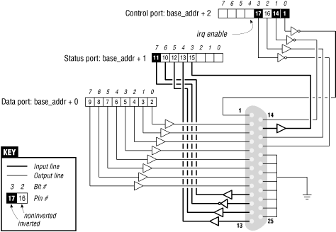
The bit specifications are outlined in Figure 8-1. You can access 12 output bits and 5 input bits, some of which are logically inverted over the course of their signal path. The only bit with no associated signal pin is bit 4 (0x10) of port 2, which enables interrupts from the parallel port. We’ll make use of this bit as part of our implementation of an interrupt handler in Chapter 9.
The driver we will introduce is called short (Simple Hardware Operations and Raw Tests). All it does is read and write a few eight-bit ports, starting from the one you select at load time. By default it uses the port range assigned to the parallel interface of the PC. Each device node (with a unique minor number) accesses a different port. The short driver doesn’t do anything useful; it just isolates for external use a single instruction acting on a port. If you are not used to port I/O, you can use short to get familiar with it; you can measure the time it takes to transfer data through a port or play other games.
For short to work on your system, it must
have free access to the underlying hardware device (by default, the
parallel interface); thus, no other driver may have allocated it.
Most modern distributions set up the parallel port drivers as modules
that are loaded only when needed, so contention for the I/O addresses
is not usually a problem. If, however, you get a “can’t get I/O
address” error from short (on the console
or in the system log file), some other driver has probably already
taken the port. A quick look at /proc/ioports
will usually tell you which driver is getting in the way. The same
caveat applies to other I/O devices if you are not using the parallel
interface.
From now on, we’ll just refer to “the parallel interface” to
simplify the discussion. However, you can set the
base module parameter at load time to redirect
short to other I/O devices. This feature
allows the sample code to run on any Linux platform where you have
access to a digital I/O interface that is accessible via
outb and inb (even though
the actual hardware is memory-mapped on all platforms but the x86).
Later, in Section 8.4, we’ll show how
short can be used with generic
memory-mapped digital I/O as well.
To watch what happens on the parallel connector, and if you have a bit of an inclination to work with hardware, you can solder a few LEDs to the output pins. Each LED should be connected in series to a 1-KΩ resistor leading to a ground pin (unless, of course, your LEDs have the resistor built in). If you connect an output pin to an input pin, you’ll generate your own input to be read from the input ports.
Note that you cannot just connect a printer to the parallel port and see data sent to short. This driver implements simple access to the I/O ports and does not perform the handshake that printers need to operate on the data.
If you are going to view parallel data by soldering LEDs to a D-type connector, we suggest that you not use pins 9 and 10, because we’ll be connecting them together later to run the sample code shown in Chapter 9.
As far as short is concerned,
/dev/short0 writes to and reads from the
eight-bit port located at the I/O address base
(0x378 unless changed at load time). /dev/short1
writes to the eight-bit port located at base + 1,
and so on up to base + 7.
The actual output operation performed by
/dev/short0 is based on a tight loop using
outb. A memory barrier instruction is used to
ensure that the output operation actually takes place and is not
optimized away.
while (count--) {
    outb(*(ptr++), address);
    wmb();
}
You can run the following command to light your LEDs:
echo -n "any string" > /dev/short0
Each LED monitors a single bit of the output port. Remember that only the last character written remains steady on the output pins long enough to be perceived by your eyes. For that reason, we suggest that you prevent automatic insertion of a trailing newline by passing the -n option to echo.
Reading is performed by a similar function, built around inb instead of outb. In order to read “meaningful” values from the parallel port, you need to have some hardware connected to the input pins of the connector to generate signals. If there is no signal, you’ll read an endless stream of identical bytes. If you choose to read from an output port, you’ll most likely get back the last value written to the port (this applies to the parallel interface and to most other digital I/O circuits in common use). Thus, those uninclined to get out their soldering irons can read the current output value on port 0x378 by running a command like:
dd if=/dev/short0 bs=1 count=1 | od -t x1
To demonstrate the use of all the I/O instructions, there are three
variations of each short device:
/dev/short0 performs the loop just shown,
/dev/short0p uses outb_p and
inb_p in place of the “fast” functions, and
/dev/short0s uses the string instructions. There
are eight such devices, from short0 to
short7. Although the PC parallel interface has
only three ports, you may need more of them if using a different I/O
device to run your tests.
The short driver performs an absolute minimum of hardware control, but is adequate to show how the I/O port instructions are used. Interested readers may want to look at the source for the parport and parport_pc modules to see how complicated this device can get in real life in order to support a range of devices (printers, tape backup, network interfaces) on the parallel port.
Get Linux Device Drivers, Second Edition now with the O’Reilly learning platform.
O’Reilly members experience books, live events, courses curated by job role, and more from O’Reilly and nearly 200 top publishers.

