This chapter focuses on use-case diagrams, which depict the functionality of a system. First, I introduce use-case diagrams and how they are used. Next, I discuss actors and use cases. Finally, I go over various relationships relating to actors and use cases. Many details that were not fleshed out in Chapter 2 are more fully elaborated here, and throughout the chapter I include suggestions relating to use-case diagrams.
Use-case modeling is a specialized type of structural modeling concerned with modeling the functionality of a system. You usually apply use-case modeling during requirements activities to capture requirements that define what a system should do. Use-case modeling typically starts early in a project and continues throughout a system development process. It is usually done as a series of workshops between users and analysts of a system in which ideas can be explored and requirements may be fleshed out over time.
As a use-case driven process uses use cases to plan and perform iterations, it is important to understand how use cases are related to one another, including what use cases have in common, which use cases are options of other use cases, and which use cases are similar to each other. Given that every project has limited resources, you can use this information about use cases to determine how best to execute a project. Use cases that are common to two or more other use cases need only be implemented once, and then they can be reused. Use cases that are options of other use cases may be implemented at a later time, and use cases that are similar allow us to implement one use case that may be reused. An understanding of how use cases are related allows users and analysts to negotiate and reach agreement concerning the scope and requirements of a system.
A use-case diagram may be considered a “table of contents” for the functional requirements of a system. The details behind each element on the use case diagram may be captured in textual form or using other UML modeling techniques. All the use-case diagrams and their associated details for a specific system form the functional requirements of the system. However, the UML does not provide any explicit guidance on how to capture the textual details, but focuses more on the notation.
As discussed in Chapter 2, an actor is a user or external system with which a system being modeled interacts. For example, our project management system involves various types of users, including project managers, resource managers, human resources, and system administrators. These users are all actors.
Actors follow the type-instance dichotomy first discussed in Chapter 2 and applied to classes and objects in Chapter 3. You can use the UML to talk about classes of actors, as well as specific actors of a class. When speaking of a class of actors, it’s customary to use the terms actor or actor class. Thus, while you might think of an actor as a specific thing, in the UML, an actor really represents a class of things. When speaking of a specific actor of a class, use the term actor instance.
An actor is external to a system, interacts with the system, may be a
human user or another system, and has goals and responsibilities to
satisfy in interacting with the system. Actors address the question
of who and what interacts with a system. In the UML, an actor is
shown as a “stick figure” icon, or
as a class marked with the actor keyword and
labeled with the name of the actor class.
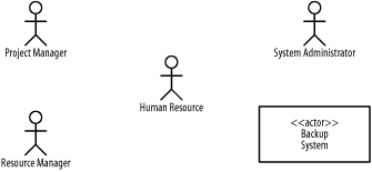
Figure 4-1 shows various actors associated with the project management system:
- A project manager
Responsible for ensuring that a project delivers a quality product within specified time and cost, and within specified resource constraints
- A resource manager
Responsible for ensuring that trained and skilled human resources are available for projects
- A human resource
Responsible for ensuring that worker skills are maintained, and that quality work is completed for a project
- A system administrator
Responsible for ensuring that a project management system is available for a project
- A backup system
Responsible for housing backup data for a project management system
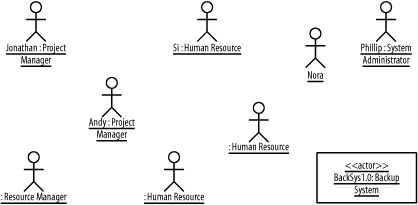
An actor instance is a specific user or system. For example, specific users of the project management system include Jonathan, Andy, Si, Phillip, Nora, and so forth. An actor instance is shown similar to an actor class, but is labeled with the actor instance name followed by a colon followed by the actor class name, all fully underlined. Both names are optional, and the colon is only present if the actor class name is specified. Actor instances address the question of who and what specifically interacts with a system.
Figure 4-2 shows various actor instances of the
actor classes in Figure 4-1, including Jonathan and
Andy who are project managers, Si who is a human resource, Phillip
who is a system administrator, Nora who is an unspecified type of
actor instance, a backup system named BackupSys1.0, and other actor
instances. Just as it’s possible to have an actor of
an unspecified type, such as Nora, it is possible to have actors such
as HumanResource for which a type is specified,
but not a name.
Because actors are external to a system and interact with that system, they define the boundary or scope of the system. For example, given the actors shown in Figure 4-1, we know exactly who and what will interact with the project management system. If we don’t define our actors, we may fall into the trap of endlessly debating whether we have identified all the users of the system and all the other systems that interact with the system. Consequentially, because every functional requirement should be of interest to at least one user (otherwise, why would we build the system to provide the functionality?), without identifying actors, we have no way of knowing whether we have identified all the functional requirements of the system. An actor may also represent a resource owned by another project or purchased rather than built. For example, the backup system must be provided by another project, and it may be purchased from a vendor or built rather than purchased. Independent of how it is developed, we are interested in interacting with it as a resource.
Get Learning UML now with the O’Reilly learning platform.
O’Reilly members experience books, live events, courses curated by job role, and more from O’Reilly and nearly 200 top publishers.

