Chapter 15. Modeling Your Deployed System: Deployment Diagrams
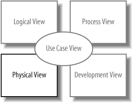
If you’ve been applying the UML techniques shown in earlier chapters of this book, then you’ve seen all but one view of your system. That missing piece is the physical view. The physical view is concerned with the physical elements of your system, such as executable software files and the hardware they run on.
UML deployment diagrams show the physical view of your system, bringing your software into the real world by showing how software gets assigned to hardware and how the pieces communicate (see Figure 15-1).
Tip
The word system can mean different things to different people; in the context of deployment diagrams, it means the software you create and the hardware and software that allow your software to run.
Deploying a Simple System
Let’s start by showing a deployment diagram of a very simple system. In this simplest of cases, your software will be delivered as a single executable file that will reside on one computer.
To show computer hardware, you use a node, as shown in Figure 15-2.
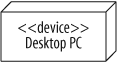
This system contains a single piece of hardware—a Desktop PC. It’s labeled with the stereotype <<device>> to specify ...
Get Learning UML 2.0 now with the O’Reilly learning platform.
O’Reilly members experience books, live events, courses curated by job role, and more from O’Reilly and nearly 200 top publishers.

