Chapter 7. Mixing Colors with an RGB LED
In this chapter, we will hook up a red, green, and blue (RGB) LED to the Mojo and use pulse-width modulation (PWM), to fade the colors in and out. We will then explore how to use the Register Interface to control the LED. The Register Interface provides a simple way to interface your designs with your computer without having to parse streams of characters in the FPGA. We will be using this to allow you to set the color of the LED from your computer.
To complete these examples, you need an RGB LED and three resistors with a value close to 330 ohms. The LED I’m using is a common anode type (LEDs share a single positive pin, and the negative sides are used to control them individually), but a common cathode LED will work as well. You may also want a breadboard and some jumper wires.
We are going to use the pins 40, 50, and 51 on the Mojo. They are located in the top-left corner and are colored red in Figure 7-1.
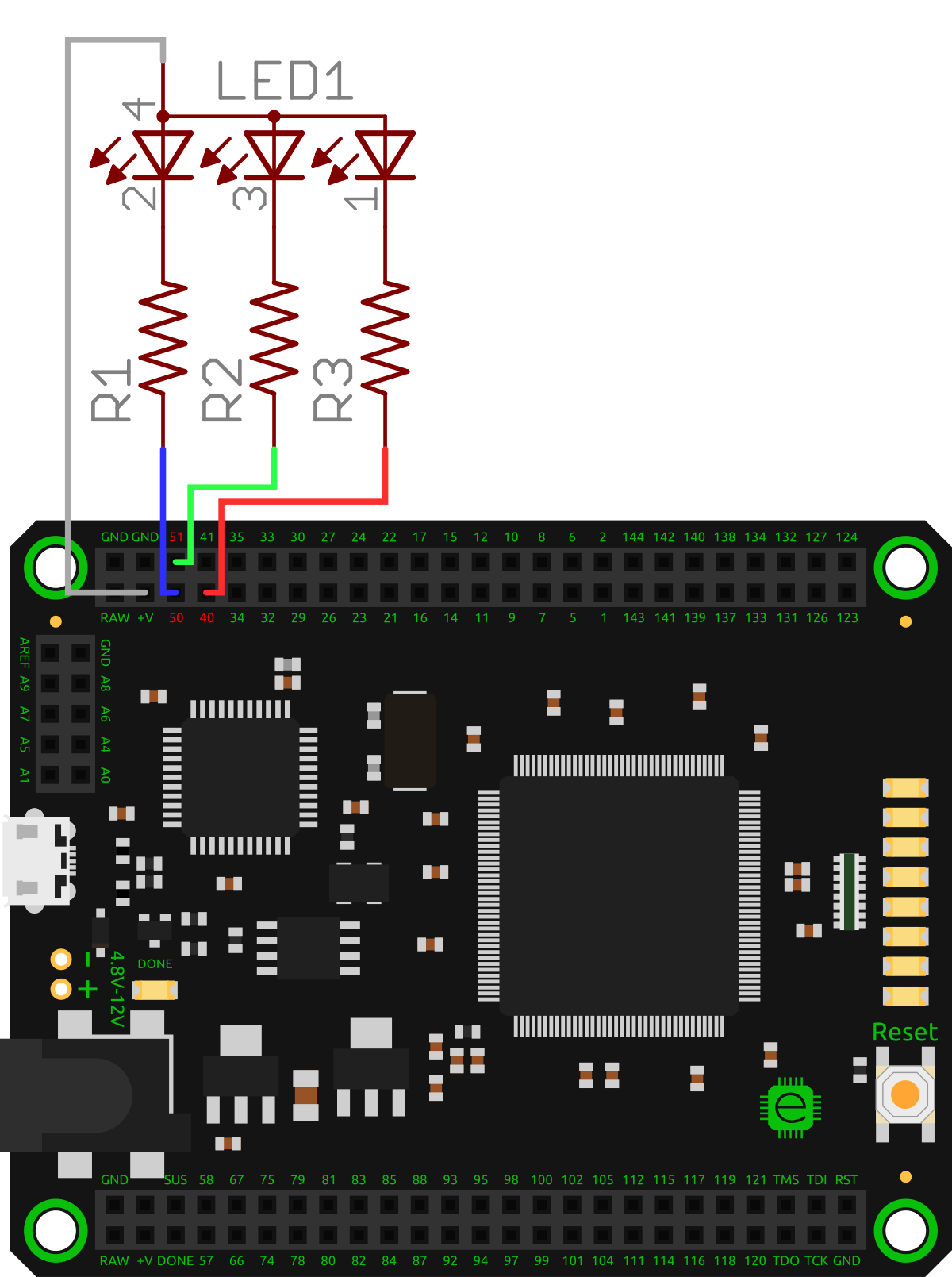
Figure 7-1. Mojo pinout with pins 40, 50, and 51 highlighted in red
Take your LED and connect the three LED color channels to the three pins. It doesn’t matter which pins you choose, as you’ll see later, but I used 40 for red, 51 for green, and 50 for blue. All that is important is that you know which is which. Make sure that you connect the LED with the resistors between it and the Mojo. If you have a common anode LED, connect the ...
Get Learning FPGAs now with the O’Reilly learning platform.
O’Reilly members experience books, live events, courses curated by job role, and more from O’Reilly and nearly 200 top publishers.

