Because most corporations have come to rely on data communications as a means of generating profit, we can safely assume that the simple design shown in Figure 1-1, with its complete lack of fault tolerance, is inadequate for the majority of corporate needs. Redundancy is necessary, so we must redesign the simple transport network.
Redundant network architectures fall into one of four basic categories:
- Redundant site architectures
Rely on identical systems and services, placed in geographically disparate locations, to support enterprise-level redundancy.
- Redundant system architectures
Rely on paired groupings of systems (routers, switches, servers) to provide service resiliency when chassis or components fail.
- Redundant component architectures
Rely on additional interface cards, processor boards, power supplies, and other major components within individual chassis to provide chassis resiliency when components fail.
- Hybrid redundancy schemes
Use a combination of system, component, and site redundancy elements to provide resilient services. This is by far the most common category.
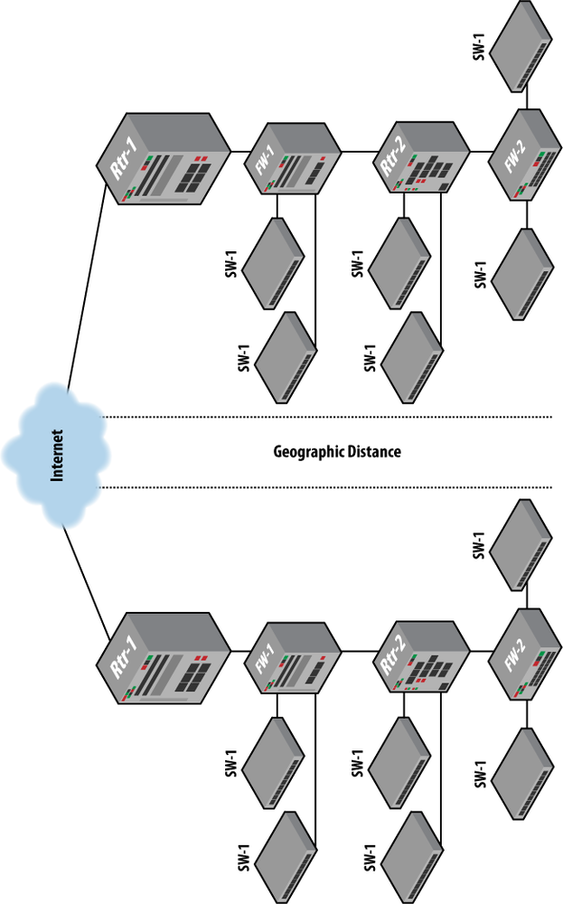
Figure 1-2 shows the simple network design from Figure 1-1 replicated at a site that is geographically distant from the primary site. The advantage of having the same architecture at two different sites is that it provides resilient routing of traffic during system or component failure, as well as during catastrophic disasters at the primary site. Also, this scheme allows the backup site to serve corporate goals because it is an online, staffed, working office while the primary site is also online.
The disadvantages of this redundancy scheme are based on usage and availability. First, note that all backup systems are physically distant from primary systems, resulting in the added difficulty of the primary site staff using the backup systems. Furthermore, this scheme by itself would require a full site failover to recover from something as simple as an interface failure on a router. Site-based redundancy schemes require constant attention, particularly when the backup site is in active use.
Resource availability on the backup system must be kept above the levels required to fully support the processing needs of the primary site. Otherwise, the backup site cannot accurately be called a backup site. For this reason and those previously listed, a site-based redundancy scheme is seldom used without some form of component or system redundancy at both the primary and backup sites.
Table 1-2 details the relative cost of a site-based redundancy scheme. Note the added cost of facilities startup as well as the annual cost of staffing, security, Internet connectivity, and utilities. You should keep in mind that any annual costs described in the table recur on a yearly basis.
Table 1-2. Relative cost of site redundancy
Line item | Description | Qty |
|---|---|---|
1 | Router 1 with interface cards and one year of vendor support | 2 |
2 | Firewall 1 with interface cards and one year of vendor support | 2 |
3 | Router 2 with interface cards and one year of vendor support | 2 |
4 | Firewall 2 with interface cards and one year of vendor support | 2 |
5 | Switch 1 and one year of vendor support | 12 |
6 | Multimode fiber trunk (materials and installation) | 20 |
7 | Additional physical facilities startup costs | 1 |
8 | Facility power and cooling for one year | 2 |
Total relative cost = $540,000 | ||
Use of redundant components within a network requires significant planning by the network architects. Equipment should be chosen that supports the component redundancy scheme required at both the physical and logical levels. To provide link redundancy, chassis should be selected that support at least twice as many physical interfaces as are needed for nonredundant connectivity. Future growth plans should also be taken into consideration.
Physical component redundancy is supported by original equipment manufacturers (OEMs) when they design a chassis to hold multiple power supplies and multiple processor boards. Logical redundancy is supported by the protocols implemented in a network. Virtual Router Redundancy Protocol (VRRP), for example, allows multiple routers or multiple interfaces on a single router to serve as virtual redundant gateways off a LAN. The Internet Engineering Task Force (IETF) standard 802.3ad, which supports bundling of multiple physical Ethernet interfaces to a single logical address, is another way to take advantage of redundant component architectures.
A disadvantage to redundant component architectures is the lack of protection in the event of complete system failure. For example, regardless of the number of redundant components within a router, a single bucket of mop water can still destroy the system. Furthermore, redundant component architectures provide no resilience against regional disasters.
Figure 1-3 shows the addition of redundant components including power supplies, processor boards, and physical connections to the simple transport network described in Figure 1-1.

Table 1-3 details the cost of the network after complete component redundancy is added. Again, costs listed are an estimate at the time of this book’s writing and may not reflect actual vendor pricing.
Note that no additional cost is associated with the implementation of logical redundancy protocols such as VRRP and 802.3ad. These protocols are relatively simple to implement and require little ongoing adjustment by network administrators. Furthermore, neither requires modification to the IP address scheme used for nonredundant connectivity.
Table 1-3. Relative cost of component redundancy
Line item | Description | Qty |
|---|---|---|
1 | Router 1 with additional interface cards and redundant power and processor and one year of vendor support | 1 |
2 | Firewall 1 with additional interface cards and redundant power and processor and one year of vendor support | 1 |
3 | Router 2 with additional interface cards and redundant power and processor and one year of vendor support | 1 |
4 | Firewall 2 with additional interface cards and redundant power and processor and one year of vendor support | 1 |
5 | Switch 1 and one year of vendor support | 6 |
6 | Multimode fiber trunk (materials and installation) | 20 |
Total relative cost = $150,000 | ||
A combination of component and site redundancy provides better network resilience than either component or site schemes do by themselves. Under the tenets of this scheme, failure of multiple components does not automatically trigger a failover to the backup site. This scheme is therefore much friendlier to both staff members and application systems. As with a simple site-based scheme, this hybrid still requires administrative attention to make sure the backup system can support resource use levels if the primary system fails.
Figure 1-4 illustrates the architectural principles of the hybrid component and site redundancy scheme applied to the simple transport network, and Table 1-4 details the relative cost associated with this scheme.

Table 1-4. Relative cost of component and site redundancy
Line item | Description | Qty |
|---|---|---|
1 | Router 1 with additional interface cards and redundant power and processor and one year of vendor support | 2 |
2 | Firewall 1 with additional interface cards and redundant power and processor and one year of vendor support | 2 |
3 | Router 2 with additional interface cards and redundant power and processor and one year of vendor support | 2 |
4 | Firewall 2 with additional interface cards and redundant power and processor and one year of vendor support | 2 |
5 | Switch 1 and one year of vendor support | 12 |
6 | Multimode fiber trunk (materials and installation) | 40 |
7 | Additional physical facilities startup costs | 1 |
8 | Additional physical facilities operational costs for one year (electricity, Internet connectivity, staffing, and support) | 1 |
Total relative cost = $660,000 | ||
Use of redundant systems within the network architecture provides protection from both component failure and complete system failure. However, this scheme provides no protection from regional disaster. You should also take into account that on top of the cost of additional systems, the power and cooling requirements of this scheme are twice those of a simple, nonredundant architecture.
The redundant system architecture requires careful planning before deployment and requires ongoing administrative scrutiny for the life of the network because, assuming traffic load is balanced across paired systems, no single physical system or single physical link is permitted to exceed 50% utilization. If any system or link does exceed 50% utilization, failure of the paired device could result in loss of data. Loss of data is not synonymous with high availability. For example, let’s say we have a traffic load evenly balanced between a pair of switches. If throughput across each of the individual switches is at 60% of individual switch capacity, then the two cannot accurately be described as a “redundant pair.” If one of the switches in the pair were to fail, then a load equivalent to 120% of single-device capacity would be placed on the remaining switch (60% + 60% = 120%). Clearly many packets would spill out on the floor, making a terrible mess!
Figures 1-5 and 1-6 show two system redundancy principles applied to infrastructure links and user LANs. These diagrams also include physical cross connection among components.
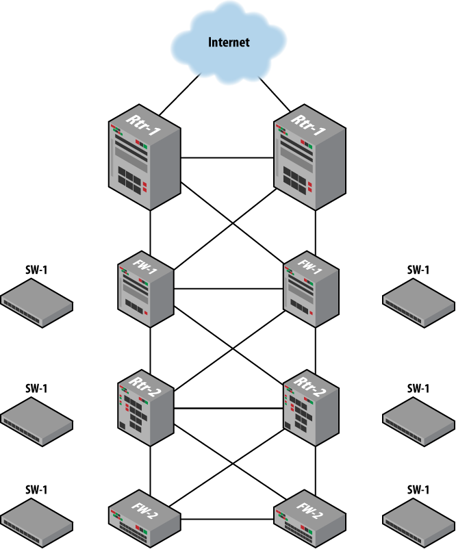
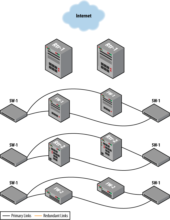
Table 1-5 shows the relative costs associated with use of redundant systems. Note the added cost of space cooling and electricity shown in the table.
Table 1-5. Relative cost of system redundancy
Line item | Description | Qty |
|---|---|---|
1 | Router 1 with interface cards and one year of vendor support | 2 |
2 | Firewall 1 with interface cards and one year of vendor support | 2 |
3 | Router 2 with interface cards and one year of vendor support | 2 |
4 | Firewall 2 with interface cards and one year of vendor support | 2 |
5 | Switch 1 and one year of vendor support | 6 |
6 | Multimode fiber trunk (materials and installation) | 28 |
7 | Additional space, cooling, and electrical use for second system | 1 |
Total relative cost = $200,000 | ||
In modern network designs, redundant systems and redundant sites are commonly used to provide effective transport network resilience. This scheme is among the more expensive; however, it does protect users from component and system failure on a local basis, as well as from regional disasters. Furthermore, this scheme allows the enterprise to take advantage of system capabilities at both the primary and backup sites. As with other architectures featuring redundant systems, care must be taken to make sure that failure of a system or a component does not result in an excessive burden on the paired device.
Figure 1-7 illustrates these system and site redundancy principles applied to our simple transport network, with Table 1-6 giving details of the relative cost of the scheme.
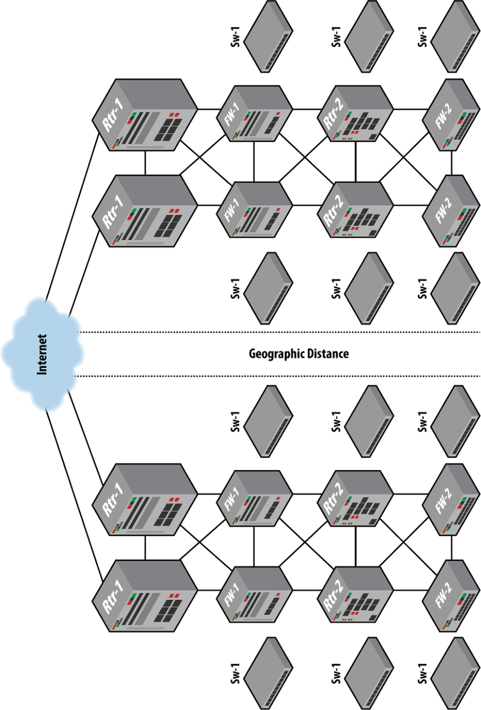
Table 1-6. Relative cost of system and site redundancy
Line item | Description | Qty |
|---|---|---|
1 | Router 1 base bundle with interface cards and one year of vendor support | 4 |
2 | Firewall 1 with interface cards and one year of vendor support | 4 |
3 | Router 2 with interface cards and one year of vendor support | 4 |
4 | Firewall 2 with interface cards and one year of vendor support | 4 |
5 | Switch 1 and one year of vendor support | 12 |
6 | Multimode fiber trunk (materials and installation) | 56 |
7 | Additional physical facilities startup costs | 1 |
8 | Additional physical facilities operational costs for one year (electricity, Internet connectivity, staffing, and support) | 1 |
Total relative cost = $720,000 | ||
Figures 1-8 and 1-9 show the combination of redundant systems and redundant components applied to the simple transport network model from Figure 1-1. This type of architecture is generally used only in situations in which an extremely strong resiliency scheme is required but site redundancy is not an option. And as itemized in Table 1-7, this scheme carries the added expense of double the amount of space, power, and cooling that would be required from a network that did not include redundant systems.
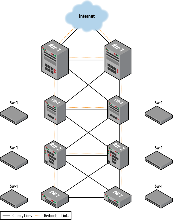
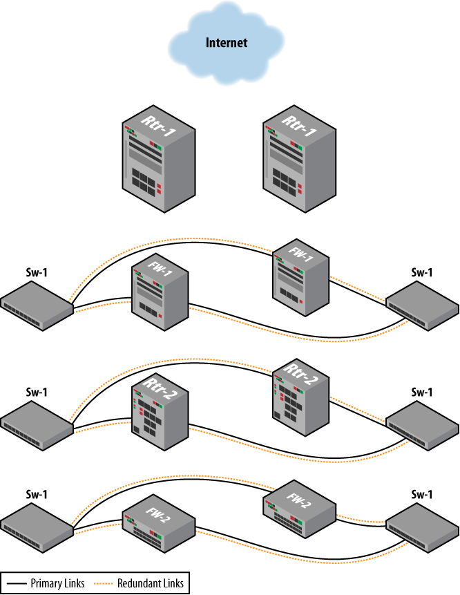
Table 1-7. Relative cost of system and component redundancy
Line item | Description | Qty |
|---|---|---|
1 | Router 1 with additional interface cards and redundant power and processor and one year of vendor support | 2 |
2 | Firewall 1 with additional interface cards and redundant power and processor and one year of vendor support | 2 |
3 | Router 2 with additional interface cards and redundant power and processor and one year of vendor support | 2 |
4 | Firewall 2 with additional interface cards and redundant power and processor and one year of vendor support | 2 |
5 | Switch 1 and one year of vendor support | 6 |
6 | Multimode fiber trunk (materials and installation) | 56 |
7 | Additional space, cooling, and electricity for second system | 1 |
Total relative cost = $320,000 | ||
The model shown in Figure 1-10 provides the greatest protection possible from equipment failure and regional disaster, though at significant cost (you’ll have to decide the price of failure for your network), as listed in Table 1-8. In comparison with the dollar amounts in Table 1-1, we can see that this scheme is almost 10 times the relative cost of a simple transport network.
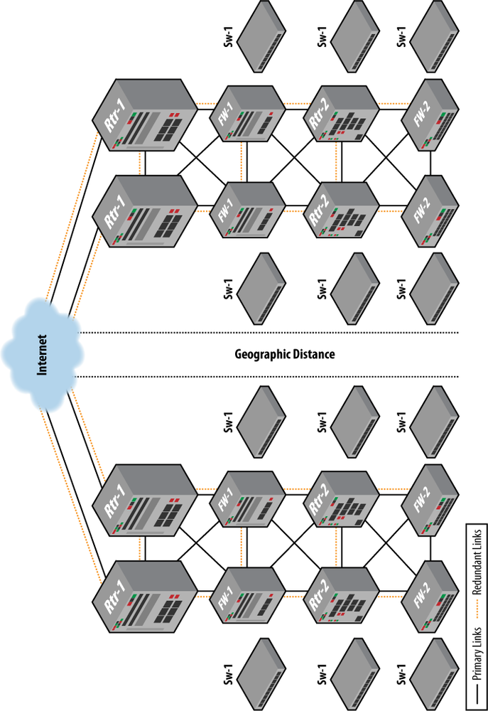
Table 1-8. Relative cost of system, component, and site redundancy
Get JUNOS High Availability now with the O’Reilly learning platform.
O’Reilly members experience books, live events, courses curated by job role, and more from O’Reilly and nearly 200 top publishers.

