This section examines current best practices for IGP migration, referring to the exchange of a networkâs existing, or legacy, IGP with a different version of IGP. Generally, the overall goals are to minimize network disruption while also taking the opportunity to improve on the networkâs design and operation. The IGP plays a critical role in the operation of any IP network. Upgrading a legacy networkâs IGP can result in dramatic performance improvements and new service capabilities, and can align a company with an open standards-based solution, which in turn facilitates a best-of-breed decision among networking boxes.
IGP migration is an excellent time to clean house, so to speak, by reevaluating all aspects of the current networkâs design. Some factors to consider include:
The potential for readdressing to better accommodate hierarchical design and route summarization
The number and types of routers needed
How those routers interconnect (WAN/LAN technologies may have evolved since the original network deployment)
Ways to improve reliability
The need to maintain high network availability may preclude significant redesign. Usually a compromise must be reached between the need for availability versus potential optimizations, based on the specifics unique to each enterprise. In some cases, a new backbone is deployed in parallel (the integration model), which affords the luxury of complete redesign at the cost of additional gear.
Before discussing specific migration approaches, it makes sense to examine some of the issues and considerations common to all approaches. General factors and concepts applying to IGP migrations include the following:
- Global route preference
IGP transitions often touch on the concept of global route preference, which is known as administrative distance in IOS. A routeâs global preference indicates the overall goodness of a source of routing information and is used to break ties when two or more protocols announce reachability to the same prefix. Recall that longest match always rules; therefore, a longest-matching RIP route will always be preferred over a less specific version (a shorter netmask) that is learned from a more preferred protocol. For example, a /24 OSPF internal route will lose to a /32 RIP route every day of the week despite its much lower, and therefore preferred, preference. Global preference breaks ties only when routes with the same level of specificity are learned by multiple routing protocols.
- Route redistribution
Route redistribution is the act of exchanging route information among different routing protocols and is a common aspect of most IGP migration strategies. In many cases, you will not configure all routers for the new IGP at the same time and will maintain connectivity between IGP domains by redistributing routes between the new and legacy IGPs at select routers. Because this will typically be mutual, also known as bidirectional route redistribution, you must remain ever-vigilant or else fall victim to the effects of routing loops. Accurate policy is needed to ensure that routes originating within IGP A that are sent into IGP B are never redistributed back into IGP A, and vice versa.
- Concurrent IGP operation
Many migration scenarios will require that a device be configured to run instances of both the old and the new IGPs at the same time. The first issue here is whether the device offers support for both protocols. For example, running EIGRP on a Juniper Networks router is simply not an option. Then there are matters of performanceâcan the device be expected to run two instances of an IGP and still operate reliably? There are numerous cases of IGP migration (ones that were planned to occur with little or no disruption, we might add) that instead melted down when a box started rebooting or peers start flapping, all because of insufficient memory or CPU power when tasked with running both IGPs concurrently. This is something that is often not considered when testing a migration scenario in a lab, where boxes may be running at far lower memory and CPU levels than they would in the production environment.
As a general rule, you can safely run both IGPs concurrently if an existing deviceâs CPU load is less than 50% while its memory load is less than 60%. If the deviceâs CPU or memory load is higher, you should consider a device upgrade or a migration approach that does not place both IGPs in service at the same time.
- Network cleanup and design
IGP migration is an opportune time to rid your network of excess baggage and poor design characteristics that may have evolved in an ad hoc fashion over the years. Before migration, you should make sure your network documentation is accurate and that you have reduced as much clutter as possible by removing any unauthorized or unneeded addresses, networks, peers, protocols, and so forth. Careful thought should be leveled at the design of the new IGP. Will it be flat or hierarchical? Does the existing addressing model accommodate? How will metrics be mapped between the old and new IGPs? Where will you place ABRs and ASBRs, and which routers should function as the DRs on LAN segments?
Several proven approaches to IGP transitions have been developed over the years, and most of these approaches share common elements to one degree or another. Each enterprise network is unique, and the specifics of your network design, your standards for acceptable levels of disruption, and your budget will come into play when deciding on a specific approach. The migration strategies are presented in an order representing easiest to most difficult. The more difficult strategies are often combined with a more extensive network redesign given the work already being performed.
The overlay model is generally considered the most straightforward IGP migration approach. The overlay is best suited to networks that have a similar before and after logical topology. For example, if the legacy network is a flat RIP network and the proposed design is a single area OSPF network, logically both networks are flat and IGP migration will be straightforward. Using an overlay approach to move from a flat to a hierarchical network can be rife with difficulties. For example, a flat networkâs addressing scheme may not accommodate a sound hierarchical design, and the placement of nodes may not accommodate the desired location or level of redundancy for things such as ABRs.
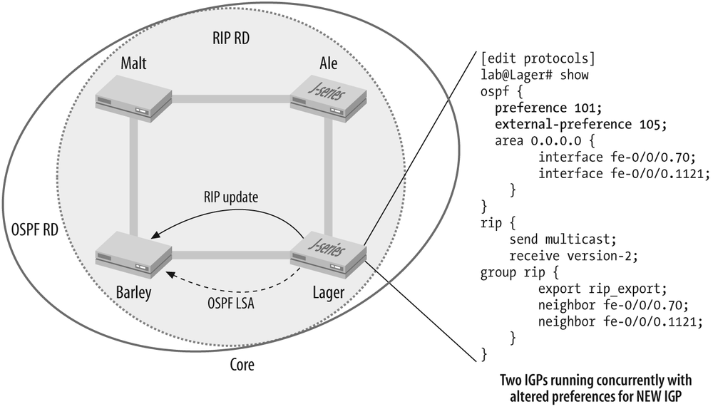
Figure 4-4 illustrates a network running both the legacy (RIP) and the new (OSPF) IGPs. Because Layer 2 switching is often used in the access and aggregation layers, the focus of most IGP migrations is centered on the core layerâthe techniques demonstrated here are applicable for access and aggregation layer migrations as well. Note how both IGPs are configured at the same time, that the new IGP is initially set to be less preferred (both OSPF preference values are larger than RIPâs default 100), and that each router sends updates for both IGPs in a ships-in-the-night fashion, meaning that neither IGP is aware of the otherâs operation.
The overlay model hinges on all devices having the ability to run
both the old and the new IGPs concurrently, and it makes heavy use of
route preference to keep the new IGPâs routes from becoming active, and
therefore installed in the forwarding table, until all aspects of the
new IGPâs operation are determined to be satisfactory. When ready to
make the cutover, the route preference is altered to have the routers
prefer the new IGPâs routes. Ideally, this is all done in parallel,
because having some devices use one IGPâs routes while other routers use
a different IGPâs routes can lead to loops stemming from variances
between each protocolâs take on the best route. In many cases, the odds
of which can be improved by the careful mapping of old to new metrics,
the forwarding paths of both protocols will be identical and you can get
away with an incremental, box-at-a-time shift in protocol preference.
When the new IGPâs operation is deemed stable, the old IGP is
decommissioned by removing its configuration from each router (there is
no need to perform this in parallel, as you are now using the new IGP).
Itâs a good idea to keep a copy of the old configuration around, and you
should consider using the deactivate
function of the JUNOS software CLI to comment out the old IGPâs stanza,
all the while knowing that you can safely bring it back at any time by
activating that portion of the configuration.
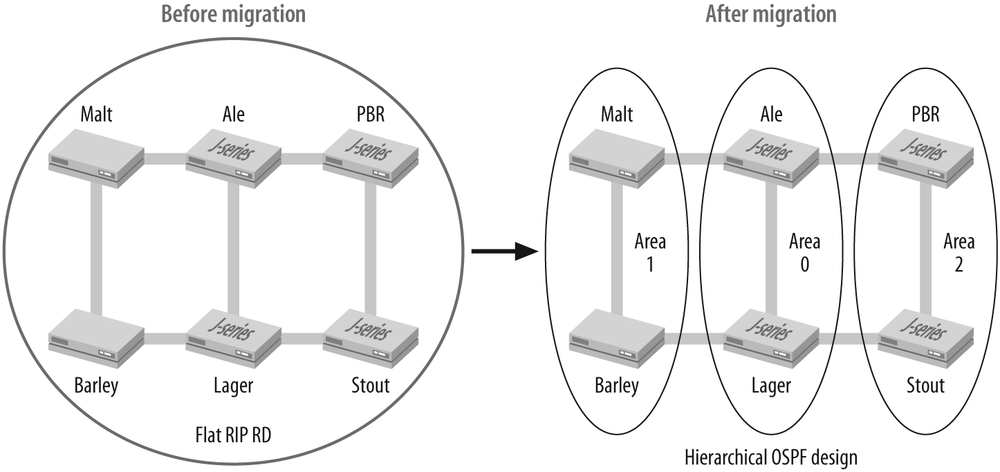
The redistribution model is often used when an overlay approach is not workable due to a migration from a flat to a hierarchical design or because some of the devices cannot run both IGPs concurrently. The latter condition may be due to lack of device support or because of performance limitations. The Redistribution Model illustrates a before-and-after view of a network that, given the shift to a hierarchical design, represents a good candidate for the route redistribution model.
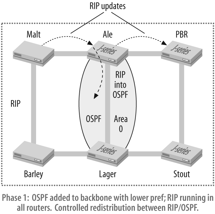
The first phase of the migration from RIP to OSPF is shown in
Figure 4-6. Here,
backbone routers Ale and Lager are configured to run both RIP and OSPF
concurrently, with the OSPF backbone being formed as a result. The arrow
shows a RIP update sent by Malt and
received by Ale, where it will be
injected into the nascent backbone as a Type 5 AS external LSA. Though
not shown, routes originating in the OSPF backbone undergo a similar
process whereby they are injected into the RIP domain to maintain full
connectivity. It is critical to stress that controls must be in place to
ensure that routes are never redistributed back into the RD from where
they originated, unless your goal is a network-wide test of the IP Time
to Live (TTL) mechanism. A well-planned addressing approach always makes
the filtering of route updates easier, as does a consistent approach to
route tagging (where supported by the protocol). The use of route tags
makes control over route redistribution much easier to configure and
consequently far less prone to human error.
Once again, the OSPF preference is altered to be less
preferred than that of the original IGP, as was the case in
the overlay model. The default global preference for JUNOS software is
100 for RIP and 10/150 for OSPF internal and AS external, respectively.
Setting these preferences to 101/110 achieves the goal of ensuring that
RIP is preferred. This step ensures that the backbone will always prefer
routes in their native RIP form, thus avoiding routing loops and
suboptimal routing. By way of example, consider that without this step,
router Barleyâs 200.0.200/24 route
might be initially learned by Lager
as an OSPF route, via a RIP update that was generated by Malt and then redistributed into OSPF by
Ale. By this time, Lager should have
also received a RIP update for the same prefix direct from Barley. If the preferences are such that
Lager prefers OSPF externals over
RIP, we would have an extra hop as Lager forwards packets for 200.0.200/24 route
over the OSPF backbone through Ale,
rather than the direct shot via Barley.
Tip
In this example, the default JUNOS software route preferences would have resulted in the desired behavior. When redistributed into OSPF, the RIP routes take the form of AS externals, which by default have a preference of 150, which makes them less preferred than RIP anyway. Nonetheless, itâs recommended that you always explicitly set preferences. Itâs rarely a good idea to leave such things to chance in your network!
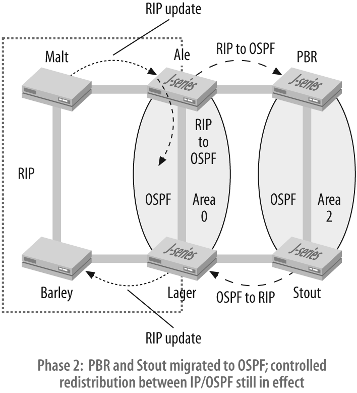
The next phase of the migration is depicted in Figure 4-7, where routers
PBR and Stout have been converted to OSPF and placed
into Area 2. The specific approach taken to make this change could have
been that of an overlay, where the routers run RIP and OSPF
concurrently, or as a hot cutover that removed the old and added the new
IGP in one fell swoop. Such cutovers are made a little less stressful
with the ânothing happens until you commitâ nature of JUNOS software.
IOS users would likely paste such changes in from a configuration file
to try to minimize disruption. It ends with routers Barley and Malt remaining in the RIP domain along with
the associated interfaces on Ale and
Lager. The next phase of the
migration is an iterative process that repeats the same procedure on
Barley and Malt to create Area 1. The IGP migration is
completed with removal of any RIP remnants from the configurations of
Area 0 routers Ale and Lager.
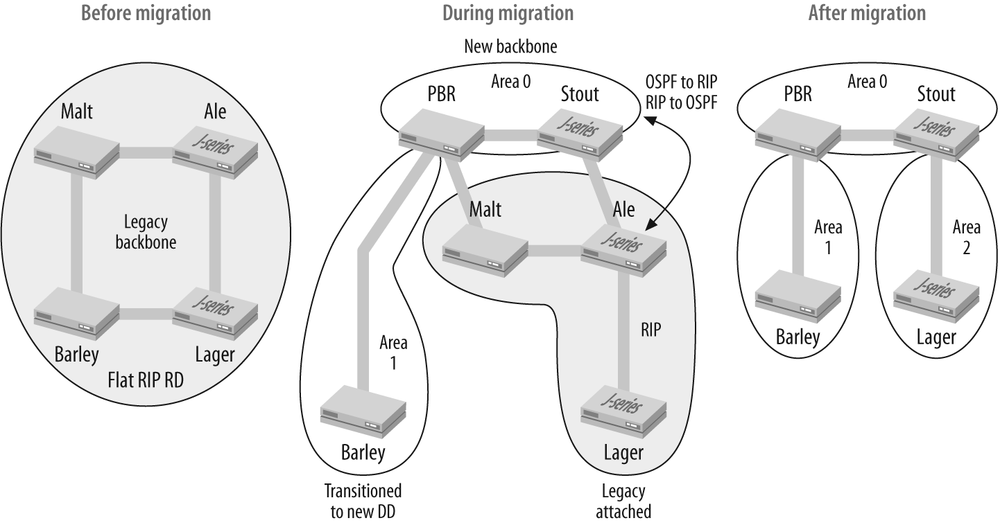
The integration model is also well suited to IGP migrations that transition from a flat to a hierarchical design, especially when a significant IP readdressing and/or network infrastructure upgrade is planned as part of the migration. In the integration model, a new backbone network is deployed and tied to the legacy backbone, where mutual route redistribution is performed. Portions of the legacy network are transitioned to the new backbone in a phased manner. This type of migration is not hitless, but its does afford a near green-field chance to redesign your IGP while confining down time to those segments that are actively being transitioned. Once all segments have been migrated to the new backbone, the legacy backbone is decommissioned. This process is shown in The Integration Model, which begins with the legacy backbone and moves on to the buildout of a new backbone and the migration of one network segment. The process ends with the rightmost diagram showing all network segments transitioned to the new backbone and removal of the legacy backbone infrastructure.
Youâll again find mutual route redistribution at play, and also this requires strict control to prevent routes from being sent back to their originating IGP. As each network segment is transitioned, you may be able to deploy an overlay approach or you might be forced into a hot cutover based on equipment capability and the level of network redesign (e.g., any renumbering that is also planned).
It goes without saying, but we will state it here anyway, that the integration model represents the largest degree of effort and capital expenditure. There is the cost of new equipment and new backbone buildout, and then the sustaining costs of both the legacy and new backbones as segments are transitioned. During these transitions, there may be significant renumbering and a need to deploy the new backbone protocol on routers as they become part of the new IGP.
Networks, like people, evolve and change over time. Many networks are still running yesterdayâs IGP and could benefit from a facelift in the interior routing department. Or maybe your network is running some proprietary routing protocol and you have decided that it is time to add another vendor to the network, for whatever reason. Either way, the techniques and concepts discussed here can help to minimize disruption and make the shift to a new IGP as pain-free as possible.
In the next section, you will put this theory into practice as you migrate a network from RIP to the OSPF protocol.
Get JUNOS Enterprise Routing now with the O’Reilly learning platform.
O’Reilly members experience books, live events, courses curated by job role, and more from O’Reilly and nearly 200 top publishers.

