When the founding engineers of Juniper decided to create routers, they took the view of forwarding packets as quickly as possible (line rate) with services enabled, which spawned the marketing decree âService without Compromise.â
All Juniper Networks routers share the same common design philosophy, which is to have a clean separation of the control and forwarding planes. In the M-series, this separation is created in hardware, whereas the J-series maintains this divide in software. The forwarding plane is referred to as the Packet Forwarding Engine (PFE), and the control plane is called the Routing Engine (RE).
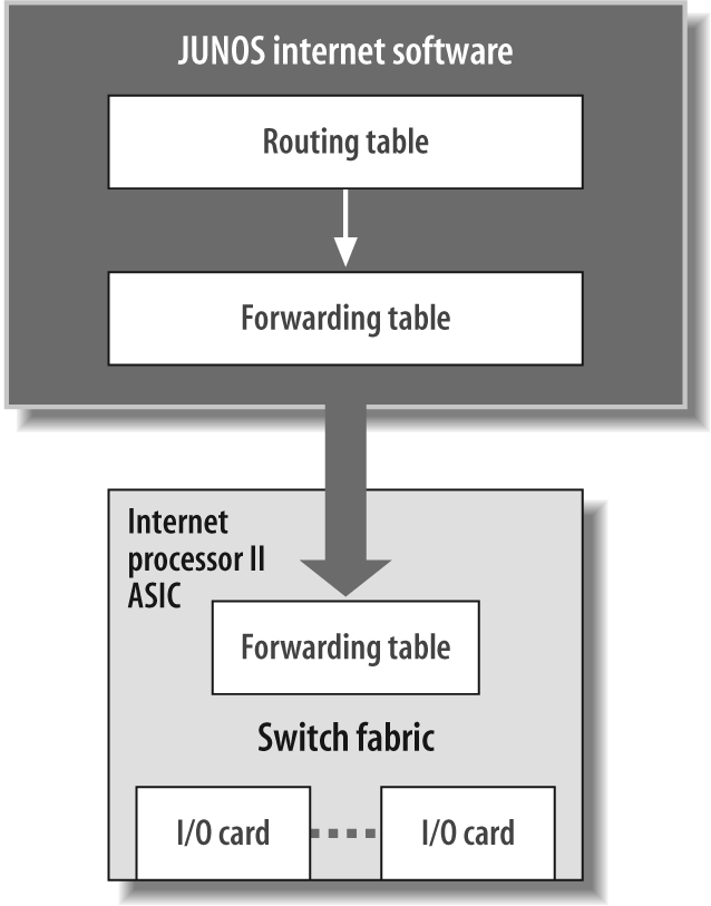
The REâs primary functions are to manage the PFE, control the routerâs software (JUNOS), manage the command-line interface (CLI), provide troubleshooting tools, and maintain the route tables and the master forwarding table. This forwarding table is passed down to the PFE and is used to forward any transit packet to the next hop destination. In this way, the RE never has to be directly involved in packet forwarding (i.e., process switching), which allows more resources for the actual control functions (see Figure 1-1). One example is the ability to issue âdebugâ commands without degrading the performance of the router!
Tip
The route table in JUNOS software is defined as all routes learned from all protocols (Open Shortest Path First [OSPF], Border Gateway Protocol [BGP0, static, interfaces, etc.]). The forwarding table provides the âbestâ routes that will be used to forward packets based on protocol preference and metrics.
The PFEâs sole purpose in life is to forward packets as fast as it can. In an M-series router, the PFE consists of several application-specific integrated circuits (ASICs) contained on various cards that are placed into the chassis. In the J-series, the PFE is a virtualized real-time thread with the ASIC functionality modeled with various APIs and sockets. Since the J-seriesâ PFE is implemented in software, we will examine it in the software section, but letâs take a brief look at the M-series now to better understand the PFE.
In an M-series router, the PFE is not just one physical card in the router, but a series of cards, each containing a different ASIC. The fundamental building block of the PFE on any M-series router is the Physical Interface Card (PIC). The PIC is the card that the physical media such as Ethernet, Serial, or Asynchronous Transfer Mode (ATM) will plug into. This PIC contains an ASIC that will pull and place data on the wire as well as deal with the actual interface framing. The final piece of the PFE is the compact Forwarding Engine Board (cFEB), which contains several ASICs that deal with packet storage, forwarding, queuing, and filtering. An M7i contains just a single cFEB, whereas an M10i will contain both a primary and a backup cFEB.
Tip
The M120 router contains six FEBs that are mapped to chassis slots and provide N+1 standby redundancy.
As previously mentioned, the PFE of a J-series router is virtualized. However, like any router in our networking universe, it must contain interfaces. The J2320, J2350, J4350, and J6350 enterprise routers have changeable cards similar to the PIC of an M-series router, called Physical Interface Modules (PIMs) or Enhanced Physical Interface Modules (EPIMs). The primary difference between a PIM and an EPIM is that EPIMs support higher-speed interfaces and must be installed in certain slots on the router.
Tip
It may seem that the two modules, PIC and PIM, essentially do the same thing, but with different nomenclature. Although this is true, there is a method behind all the madness, as PIMs can be used only in J-series routers and PICs can be used only in M/T-series devices.
Get JUNOS Enterprise Routing now with the O’Reilly learning platform.
O’Reilly members experience books, live events, courses curated by job role, and more from O’Reilly and nearly 200 top publishers.

