ISSU Lab
This section demonstrates several Junos HA features working together to support an ISSU. Namely GRES, NSR, and, of course, the ISSU feature itself. Figure 9-17 shows the modified lab topology for ISSU testing.
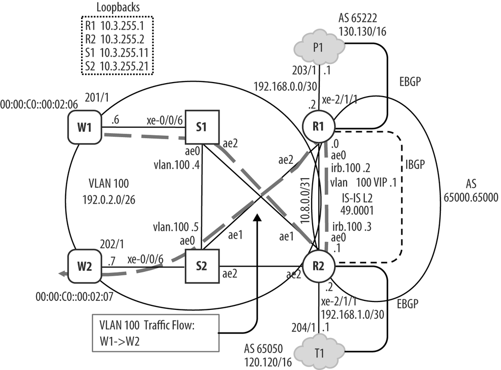
Figure 9-17. ISSU Test Topology.
As R1 has been getting all the attention lately, the plan has R2 being upgraded from its current 11.4R1.9 to 11.4R2.8. The primary modification, aside from the new Device under Test (DUT), is the deactivation of the ae1 interface at R1. This is done to force the Layer 2 traffic in VLAN 100 over the ae0 link, thereby placing R2 into the forwarding path for both the Layer 2 and Layer 3 traffic. The BGP traffic flows as in the previous NSR section, but now, VLAN 100 traffic arriving at S1’s xe-0/0/6 interface is sent to R2 via its ae2 interface. Once there, the traffic is sent to R1 via the ae0 link, where it’s then sent out R1’s ae2 to reach S2 and the destination tester port; this convoluted forwarding path is shown on Figure 9-17 via the dashed line. Traffic sourced at S2 takes a similar path, going out its ae1 to R1, then out R1’s ae0 over to R2, and then out R2’s ae1 to reach the destination switch S1.
As noted previously, the result is that now both the Layer 2 and
Layer 3 test traffic must transit the ae0 link between R1 and R2. The
result is confirmed with a monitor interface
ae0 command at R1 while all four streams are flowing:
R2-RE0 ...
Get Juniper MX Series now with the O’Reilly learning platform.
O’Reilly members experience books, live events, courses curated by job role, and more from O’Reilly and nearly 200 top publishers.

