Multi-Chassis Link Aggregation
MC-LAG allows a client device to establish IEEE 802.3ad across two physically separate chassis. A key differentiator is that MC-LAG maintains a separate control plane for each chassis that participates in the MC-LAG, as opposed to MX-VC where there also are two physical chassis, but the two control planes are virtualized into a single control plane.
Typically, when you setup IEEE 802.3ad it’s only between two devices; the upside is that you now have link-level redundancy and more bandwidth, but the downside is that there isn’t node-level redundancy. MC-LAG allows you to split the IEEE 802.3ad across two chassis to provide the node-level redundancy that’s previously been missing when using vanilla IEEE 802.3ad. Let’s take a look at a vanilla IEEE 802.3ad topology, as shown in Figure 8-1.
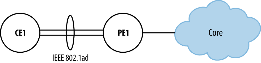
Figure 8-1. Vanilla IEEE 802.3ad
You can see that CE1 is connected
to PE1 via IEEE 802.3ad, which contains
two child links. The obvious benefit is that CE1 now has twice the bandwidth because there
are two child members and is able to survive a single link failure. If
PE1 were to fail, unfortunately that
would leave CE1 in the dark and unable
to forward traffic to the core. What’s needed is node-level redundancy on
the provider side. The astute reader already realizes that vanilla IEEE
802.3ad will not work across multiple devices; that is where MC-LAG comes
in.
If the provider ...
Get Juniper MX Series now with the O’Reilly learning platform.
O’Reilly members experience books, live events, courses curated by job role, and more from O’Reilly and nearly 200 top publishers.

