Chapter 4. ICMPv6
If you are familiar with IPv4, the Internet Control Message Protocol (ICMP) for IPv4 is probably a good friend of yours: it gives important information about the health of the network. ICMPv6 is the version that works with IPv6. It reports errors if packets cannot be processed properly and sends informational messages about the status of the network. For example, if a router cannot forward a packet because it is too large to be sent out on another network, it sends an ICMP message back to the originating host. The source host can use this ICMP message to determine a better packet size and then resend the data. ICMP also performs diagnostic functions, such as the well-known ping, which uses ICMP Echo Request and Echo Reply messages to test availability of a node.
ICMPv6 is much more powerful than ICMPv4 and contains new functionality, as described in this chapter. For instance, the Internet Group Management Protocol (IGMP) function that manages multicast group memberships with IPv4 has been incorporated into ICMPv6. The same is true for ARP/RARP, the Address Resolution Protocol/Reverse Address Resolution Protocol function used in IPv4 to map Layer 2 addresses to IP addresses (and vice versa). Neighbor Discovery (ND) is introduced; it uses ICMPv6 messages to determine link-layer addresses for neighbors attached to the same link, find routers, keep track of which neighbors are reachable, and detect changed link-layer addresses. New message types have been defined to allow for simpler renumbering of networks and updating of address information between hosts and routers. ICMPv6 also supports Mobile IPv6, which is described in Chapter 8. ICMPv6 is part of IPv6, and it must be implemented fully by every IPv6 node. The protocol is defined in RFC 4443. Neighbor Discovery is defined in RFC 4861.
General Message Format
All ICMPv6 messages have the same general header structure, as shown in Figure 4-1.
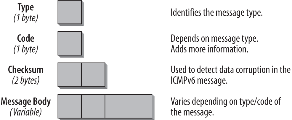
- Type (1 byte)
- This field specifies the type of message, which determines the format of the remainder of the message. Tables 4-1 and 4-2 list ICMPv6 message types and numbers.
- Code (1 byte)
- The Code field depends on the message type and allows for more granular information in certain cases. Refer to Tables 4-1 and 4-2 for a detailed list.
- Checksum (2 bytes)
- The Checksum field is used to detect data corruption in the ICMPv6 header and in parts of the IPv6 header. In order to calculate the checksum, a node must determine the Source and Destination address in the IPv6 header. There is a pseudoheader included in the checksum calculation, which is new with ICMPv6. Chapter 5 discusses the checksum and the pseudoheader.
- Message body (variable size)
- Depending on the type and code, the message body will hold different data. In the case of an error message, to assist in troubleshooting, it will contain as much as possible of the packet that invoked the message. The total size of the ICMPv6 packet should not exceed the minimum IPv6 MTU, which is 1,280 bytes. Tables 4-1 and 4-2 provide an overview of the different message types, along with the additional code information, which depends on the message type.
There are two classes of ICMP messages:
- ICMP error messages
- Error messages have a 0 in the high-order bit of their message Type field. ICMP error message types are, therefore, in the range from 0 to 127.
- ICMP informational messages
- Informational messages have a 1 in the high-order bit of their message Type field. ICMP informational message types are, therefore, in the range from 128 to 255.
An IPv6 header and zero or more Extension headers precede every ICMPv6 message. The header just preceding the ICMP header has a Next Header value of 58. This value is different from the value for ICMPv4 (which has the value 1).
Note
The values for the Next Header field are discussed in Chapter 3.
The following message types are described in RFC 4443:
ICMPv6 error messages
- Destination Unreachable (message type 1)
- Packet Too Big (message type 2)
- Time Exceeded (message type 3)
- Parameter Problem (message type 4)
ICMPv6 informational messages
- Echo Request (message type 128)
- Echo Reply (message type 129)
Note
For the most current list of ICMPv6 message types, refer to the Internet Assigned Number Authority (IANA) at http://www.iana.org/assignments/icmpv6-parameters. All IPv4 ICMP parameters can be found at http://www.iana.org/assignments/icmp-parameters.
| Message number | Message type | Code field |
1 | Destination Unreachable |
|
2 | Packet Too Big | Code field set to |
3 | Time Exceeded |
|
4 | Parameter Problem |
The pointer field identifies the octet offset within the invoking packet where the error was detected. The pointer points beyond the end of the ICMPv6 packet if the field in error is beyond what can fit in the maximum size of an ICMPv6 error message. |
100 and 101 | Private experimentation | RFC 4443 |
127 | Reserved for expansion of ICMPv6 error messages | RFC 4443 |
Note that the message numbers and types have substantially changed compared to ICMPv4. ICMP for IPv6 is a different protocol, and the two versions of ICMP are not compatible. Your analyzer, such as Wireshark, should properly decode all this information, so you do not have to worry about memorizing it.
Message number | Message type | Description |
128 | Echo Request | RFC 4443. Used for the ping command. |
129 | Echo Reply | Â |
130 | Multicast Listener Query | RFC 2710. Used for multicast goup management. |
131 | Multicast Listener Report | Â |
132 | Multicast Listener Done | Â |
133 | Router Solicitation | RFC 4861. Used for Neighbor Discovery and Autoconfiguration. |
134 | Router Advertisement | Â |
135 | Neighbor Solicitation | Â |
136 | Neighbor Advertisement | Â |
137 | Redirect Message | Â |
138 | Router Renumbering | RFC 2894 Codes:
|
139 | ICMP Node Information Query | RFC 4620 |
140 | ICMP Node Information Response | Â |
141 | Inverse ND Solicitation | RFC 3122 |
142 | Inverse ND Adv Message | RFC 3122 |
143 | Version 2 Multicast Listener Report | RFC 3810 |
144 | ICMP Home Agent Address Discovery Request Message | RFC 6275, âICMPv6 Messages for Mobile IPv6â |
145 | ICMP Home Agent Address Discovery Reply Message | Â |
146 | ICMP Mobile Prefix Solicitation Message | Â |
147 | ICMP Mobile Prefix Advertisement Message | Â |
148 | Certification Path Solicitation Message | RFC 3971 âICMPv6 Messages for SEcure Neighbor Discoveryâ |
149 | Certification Path Advertisement Message | Â |
151 | Multicast Router Advertisement | RFC 4286 |
152 | Multicast Router Solicitation | Â |
153 | Multicast Router Termination | Â |
154 | Fast Mobile IPv6 Messages | RFC 5568 |
155 | Routing Protocol for Low-Power Network Messages | RFC 6550 |
156 | ILNPv6 Locator Update Message | RFC 6743 |
157 | Duplicate Address Request | RFC 6775 (6LoWPANs) |
158 | Duplicate Address Confirmation | Â |
200 and 201 | Private experimentation | RFC 4443 |
255 | Reserved for expansion of ICMPv6 informational messages | RFC 4443 |
With the exception of the router renumbering message (138), the ICMPv6 informational messages do not use the Code field. It is, therefore, set to zero.
As you will learn in the coming paragraphs, ICMPv6 is very powerful and is used for many processes that are critical to the proper working of IPv6, such as Path MTU Discovery. Therefore it is not a good idea to completely filter all ICMP messages at firewalls, as has been the practice in many IPv4 networks. With ICMPv6 you have to carefully evaluate which ICMPv6 messages are important. RFC 4890, âRecommendations for Filtering ICMPv6 Messages in Firewalls,â discusses this and makes recommendations.
ICMP Error Messages
Every ICMP message can have a slightly different header depending on the kind of error report or information it carries. The following sections outline the structure of each type of ICMPv6 message.
Destination Unreachable
A Destination Unreachable message is generated if an IP datagram cannot be delivered. A Type field with the value 1 identifies this message. The ICMP message is sent to the Source address of the invoking packet. The format of the Destination Unreachable message is shown in Figure 4-2.
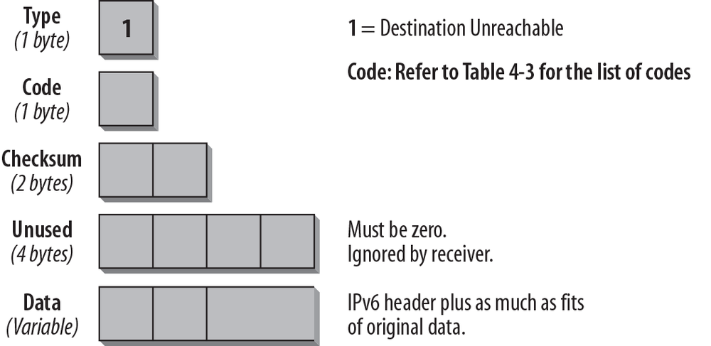
The Type field is set to 1, which is the value for the Destination Unreachable message. The Code field supplies more information about the reason why the datagram was not delivered. The possible codes are listed in Table 4-3. The data portion of the ICMP message contains as much of the original message as will fit into the ICMP message.
| Code | Description |
0 | âNo route to destination.â This code is used if a router cannot forward a packet because it does not have a route in its table for a destination network. This can happen only if the router does not have an entry for a default route. |
1 | âCommunication with destination administratively prohibited.â This type of message can, for example, be sent by a firewall that cannot forward a packet to a host inside the firewall because of a packet filter. It might also be sent if a node is configured not to accept unauthenticated Echo Requests. |
2 | âBeyond scope of Source address.â This code is used if the Destination address is beyond the scope of the Source address, e.g., if a packet has a link-local Source address and a global Destination address. |
3 | âAddress unreachable.â This code is used if a Destination address cannot be resolved into a corresponding network address or if there is a data-link layer problem preventing the node from reaching the destination network. |
4 | âPort unreachable.â This code is used if the transport protocol (e.g., UDP) has no listener and there is no other means to inform the sender. For example, if a Domain Name System (DNS) query is sent to a host and the DNS server is not running, this type of message is generated. |
5 | âSource address failed ingress/egress policy.â This code is used if a packet with this Source address is not allowed due to ingress or egress filtering policies. |
6 | âReject route to destination.â This code is used if the route to the destination is a reject route. |
If the destination is unreachable due to congestion, no ICMP message is generated. A host that receives a Destination Unreachable message must inform the upper-layer process.
Packet Too Big
If a router cannot forward a packet because it is larger than the MTU of the outgoing link, it will generate a Packet Too Big message (shown in Figure 4-3). This ICMPv6 message type is used as part of the Path MTU Discovery process that I discuss later in this chapter. The ICMP message is sent to the Source address of the invoking packet.
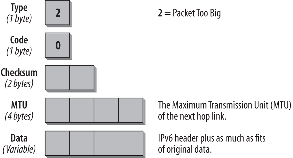
The Type field has the value 2, which identifies the Packet Too Big message. In this case, the Code field is not used and is set to 0. The important information for this type of message is the MTU field, which contains the MTU size of the next hop link.
RFC 4443 states that an ICMPv6 message should not be generated as a response to a packet with an IPv6 multicast Destination address, a link-layer multicast address, or a link-layer broadcast address. The Packet Too Big message is an exception to this rule. Because the ICMP message contains the supported MTU of the next hop link, the source host can determine the MTU that it should use for further communication. A host that receives a Packet Too Big message must inform the upper-layer process.
Time Exceeded
When a router forwards a packet, it always decrements the hop limit by one. The hop limit makes sure that a packet does not endlessly travel through a network. If a router receives a packet with a hop limit of 1 and decrements the limit to 0, it discards the packet, generates a Time Exceeded message with a code value of 0, and sends this message back to the source host. This error can indicate a routing loop or the fact that the senderâs initial hop limit is too low. It can also tell you that someone used the traceroute utility, which is described later in this chapter. Figure 4-4 shows the format of the Time Exceeded message.
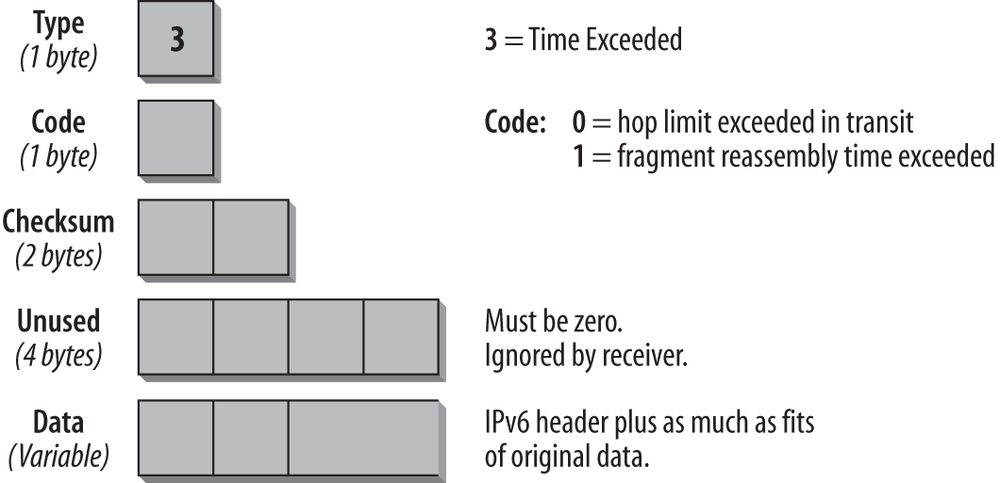
The Type field carries the value 3, specifying the Time Exceeded message. The Code field can be set to 0, which means the hop limit was exceeded in transit, or to 1, which means that the fragment reassembly time is exceeded. The data portion of the ICMP message contains as much of the original message as will fit into the ICMP message, depending on the MTU used.
An incoming Time Exceeded message must be passed to the upper-layer process. Table 4-4 shows the Code fields for the Time Exceeded message.
| Code | Description |
0 | âHop limit exceeded in transit.â Possible causes: the initial hop limit value is too low; there are routing loops; or use of the traceroute utility. |
1 | âFragment reassembly time exceeded.â If a fragmented packet is sent by using a fragment header (refer to Chapter 2 for more details) and the receiving host cannot reassemble all packets within a certain time, it notifies the sender by issuing this ICMP message. |
The âHop limit exceeded in transitâ message type is commonly used to do the traceroute function. Traceroute is helpful in determining the path that a packet takes when traveling through the network. In order to do this, a first packet is sent out with a hop limit of 1. The first router in the path decrements the hop limit to 0, discards the packet, and sends back an ICMP message type 3, code 0. The source host now knows the address of the first hop router. Next, it sends out a second packet with a hop limit of 2. This packet is forwarded by the first router, which decrements the hop limit to 1. The second router in the path decrements the hop limit to 0, discards the packet, and sends back an ICMP message type 3, code 0. Now the source knows about the second router in the path. Raising the hop limit by one (with every packet sent until the packet reaches the final destination) continues this process. Every router in the path to the final destination sends an ICMP message back to the source host, thereby providing its IP address. It is important to know that if there are redundant paths to the destination, traceroute does not necessarily show the same route for all tests because it might choose different paths.
Parameter Problem
If an IPv6 node cannot complete the processing of a packet because it has a problem identifying a field in the IPv6 header or in an Extension header, it must discard the packet, and it should send an ICMP Parameter Problem message back to the source of the problem packet. This type of message is often used when an error that does not fit into any of the other categories is encountered. The format of this ICMP message is shown in Figure 4-5.
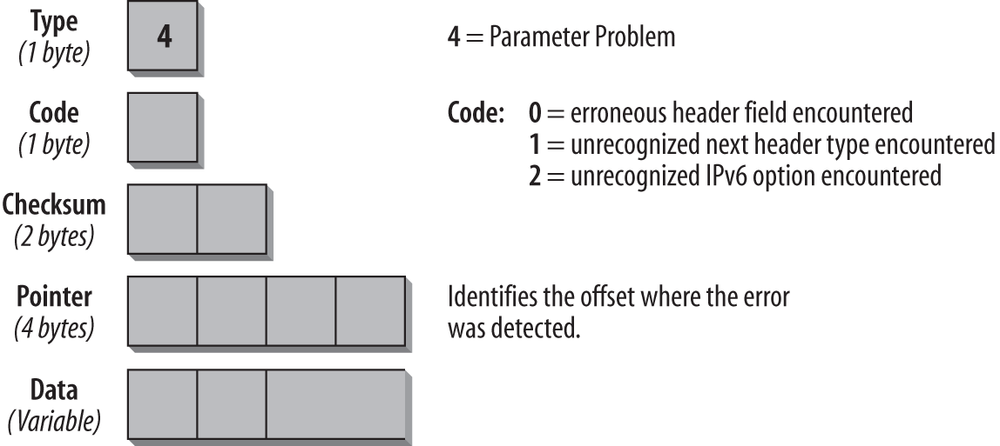
The Type field has the value 4, which specifies the Parameter Problem message. The Code field can contain any of the three values described in Table 4-5. The Pointer field identifies at which byte in the original packet the error was detected. The ICMP message includes as much of the original data as fits, up to the minimum IPv6 MTU. It is possible that the pointer points beyond the ICMPv6 message. This would be the case if the field in error was beyond what can fit in the maximum size of an ICMPv6 error message.
Table 4-5 shows the Code fields for the Parameter Problem message.
| Code | Description |
0 | Erroneous header field encountered |
1 | Unrecognized next header type encountered |
2 | Unrecognized IPv6 option encountered |
For example, an ICMPv6 message of type 4 with a code value of 1 and a pointer set to 40 indicates that the Next Header type in the header following the IPv6 header was unrecognized.
An incoming Parameter Problem message must be passed to the upper-layer process.
ICMP Informational Messages
In RFC 4443, two types of informational messages are defined: the Echo Request and the Echo Reply messages. Other ICMP informational messages are used for Path MTU Discovery and Neighbor Discovery. These messages are discussed at the end of this chapter and defined in RFC 4861, âNeighbor Discovery for IP Version 6,â and RFC 1981, ââPath MTU Discoveryâ for IP Version 6.â
The Echo Request and Echo Reply messages are used for one of the most common TCP/IP utilities: Packet InterNet Groper (ping). Ping is used to determine whether a specified host is available on the network and ready to communicate. The source host issues an Echo Request message to the specified destination. The destination host, if available, responds with an Echo Reply message. Figures 4-8 and 4-9 (later in the chapter) show what a ping looks like in the trace file.
Echo Request Message
The format of the Echo Request message is shown in Figure 4-6.
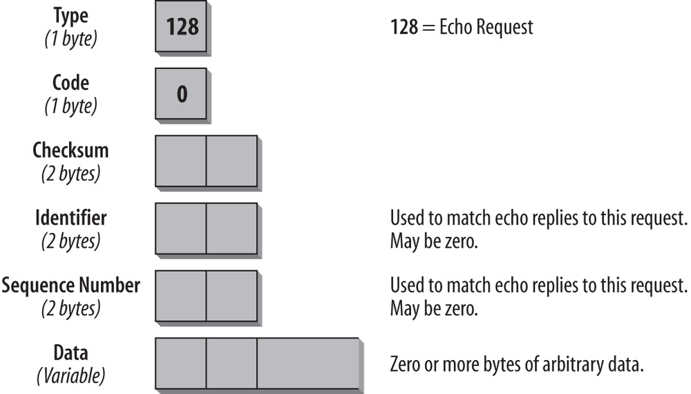
The Type field is set to 128, the value for the Echo Request. The Code Field is not used for this message and is therefore set to 0. The Identifier and Sequence Number fields are used to match requests with replies. The reply must always contain the same numbers as the request. Whether an identifier and a sequence number are used and what kind of arbitrary data is included in the Echo Request depends on the TCP/IP stack you are using. When you analyze trace files with Echo Request and Echo Reply messages and you are familiar with some stacks, you can determine the TCP/IP stack of the sender by looking at the arbitrary data.
Echo Reply
The format of the Echo Reply message is very similar to that of the Echo Request, as shown in Figure 4-7.
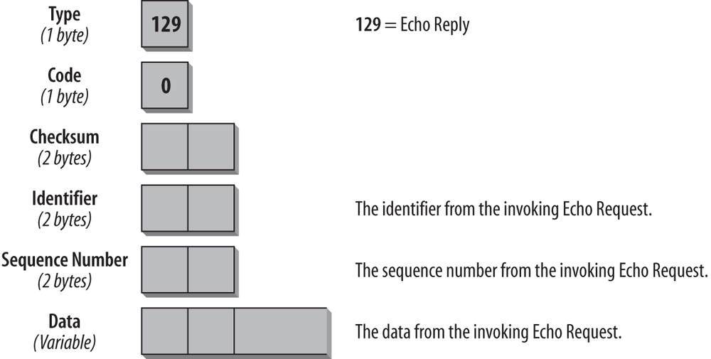
The Type field contains the value 129 for Echo Reply. The Code field is unused and set to 0. The Identifier and Sequence Number fields must match the fields in the request. The data of the Echo Request message must be copied into the reply entirely and unmodified. If an upper-layer process initiated the Echo Request, the reply must be passed to that process. If the Echo Request message was sent to a unicast address, the Source address of the Echo Reply message must be the same as the Destination address of the Echo Request message. If the Echo Request was sent to an IPv6 multicast address, the Source address of the Echo Reply must be a unicast address of the interface on which the multicast Echo Request was received.
According to the specification, ICMPv6 Echo Request and Reply messages can be authenticated, using an IPv6 authentication header. This means that a node can be configured to ignore nonauthenticated ICMPv6 pings and provide protection against different ICMPv6 attacks. I donât know of any implementation, though, that supports this feature.
Processing Rules
There are several rules that govern processing of ICMP packets. They can be found in RFC 4443 and are summarized as follows:
- If a node receives an ICMPv6 error message of unknown type, it must pass it to the upper layer.
- If a node receives an ICMPv6 informational message of unknown type, it must be silently discarded.
- As much as possible of the packet that caused the ICMP error message will be included in the ICMP message body. The ICMP packet should not exceed the minimum IPv6 MTU.
- If the error message has to be passed to the upper-layer protocol, the protocol type is determined by extracting it from the original packet (present in the body of the ICMPv6 error message). In case the protocol type cannot be found in the body of the ICMPv6 message (because there were too many Extension headers present in the original packet, and the part of the header that contained the upper-layer protocol type was truncated), the ICMPv6 message is silently discarded.
An ICMPv6 error message must not be sent in the following cases:
- As a result of an ICMPv6 error message.
- As a result of an ICMPv6 redirect message.
- As a result of a packet sent to an IPv6 multicast address. There are two exceptions to this rule: the Packet Too Big message that is used for Path MTU Discovery, and the Parameter Problem with the code value 2 for an unrecognized IPv6 option.
- As a result of a packet sent as a link-layer multicast (exceptions just described apply).
- As a result of a packet sent as a link-layer broadcast (exceptions just described apply).
- As a result of a packet whose Source address does not uniquely identify a single node. This could be an IPv6 unspecified address, an IPv6 multicast address, or an IPv6 address known to be an anycast address.
Every IPv6 node must implement a rate-limiting function that limits the rate of ICMPv6 messages it sends, and it should be configurable. If this function is implemented properly, it protects against Denial of Service attacks.
The ICMPv6 Header in a Trace File
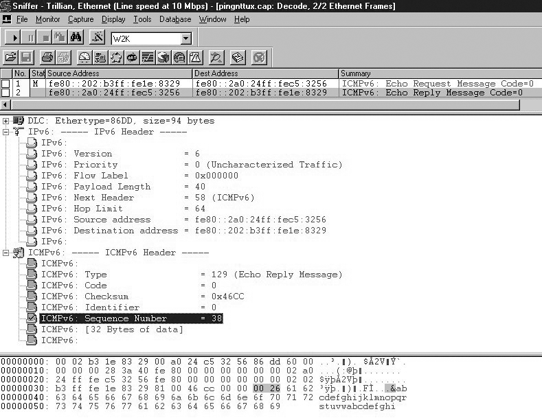
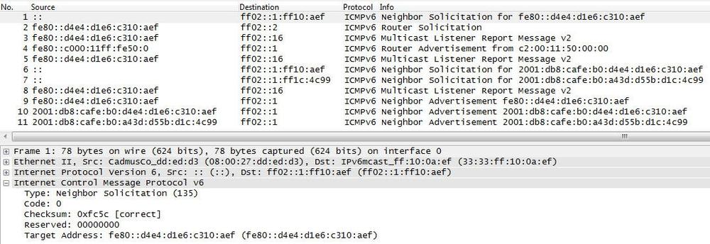
After reading through all that dry information, you deserve something different. The following screenshot (Figure 4-8) shows what a ping looks like in the trace file and provides details of many of the fields discussed so far.
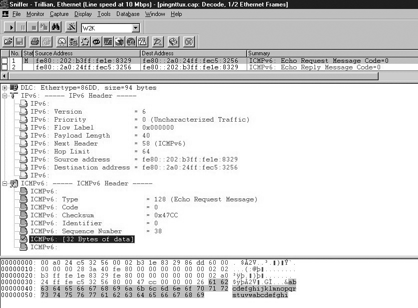
As shown in Chapter 3, the IPv6 header provides the following information: the Version field is set to 6 and indicates that this is an IPv6 packet. Priority and Flow Label are not configured and set to zero. The Payload Length field is set to 40 bytes. The Next Header field has the value 58, which is the value for ICMPv6. The Hop Limit is set to 64. We can also see source and destination IP address. The prefix fe80: indicates that these two addresses are link-local addresses.
Note the first three fields of the ICMPv6 header. They are the fields that are common for every ICMPv6 message: the Type, Code, and Checksum fields. The Type field contains the value 128, which is the value for an Echo Request. The Identifier and Sequence Number fields are unique to the Echo Request and Echo Reply message. The Identifier is not used in this case, and the sender has set the sequence to 38. It has to be identical in the matching reply shown in the following screenshot. The Data field contains arbitrary data that doesnât need to make sense to anyone.
Oh, I almost forgot that earlier I promised to show vendor stack-related data in the Echo Request message. What you see hereâthe alphabet up to the letter âwââis what Microsoft uses. Whenever you see this in a trace file, a Microsoft stack is sending the request. Figure 4-9 shows the Echo Reply in detail.
Again, the IPv6 header shows a value of 6 for the IP version and a Next Header value of 58 for ICMPv6. The Destination address of the previous frame is now the Source address, and the previous Source address is now the Destination address. The Type field in the ICMPv6 header shows a value of 129, which is the value for an Echo Reply. The Identifier and Sequence Number fields, as well as the Data field, match the ones in the Echo Request.
Neighbor Discovery
Neighbor Discovery (ND) is specified in RFC 4861. The specifications in this RFC relate to different protocols and processes known from IPv4 that have been modified and improved. New functionality has also been added. It combines Address Resolution Protocol (ARP) and ICMP Router Discovery and Redirect. With IPv4, we have no means to detect whether a neighbor is reachable. With the Neighbor Discovery protocol, a Neighbor Unreachability Detection (NUD) mechanism has been defined. Duplicate IP address detection (DAD) has also been implemented. IPv6 nodes use Neighbor Discovery for the following purposes:
- For Stateless Autoconfiguration of IPv6 addresses
- To determine network prefixes, routes, and other configuration information
- For Duplicate IP Address Detection (DAD)
- To determine Layer 2 addresses of nodes on the same link
- To find neighboring routers that can forward their packets
- To keep track of which neighbors are reachable and which are not (NUD)
- To detect changed link-layer addresses
The following improvements over the IPv4 set of protocols can be noted:
- Router Discovery is now part of the base protocol set. With IPv4, the mechanism needs to get the information from the routing table or DHCP.
- Router Advertisement packets contain link-layer addresses for the router. There is no need for the node receiving a Router Advertisement to send out an additional ARP request (as an IPv4 node would have to do) to get the link-layer address for the router interface. The same is true for ICMPv6 Redirect messages; they contain the link-layer address of the new next-hop router interface.
- Router Advertisement packets contain the prefix for a link (subnet information). There is no longer a need to configure subnet masks; they can be learned from the Router Advertisement.
- Neighbor Discovery (ND) provides mechanisms to renumber networks more easily. New prefixes and addresses can be introduced while the old ones are still in use, and the old ones can be deprecated and removed gradually.
- Router Advertisements enable Stateless Address Autoconfiguration and can tell hosts when to use Stateful Address Configuration (e.g., DHCP).
- Routers can advertise an MTU to be used on a link.
- Multiple prefixes can be assigned to one link. By default, hosts learn all prefixes from the router, but the router can be configured not to advertise some or all of the prefixes. In that case, hosts assume that a nonadvertised prefix destination is remote and send the packets to the router. The router can then issue ICMP Redirect messages as needed.
- Neighbor Unreachability Detection (NUD) is part of the base protocol. It substantially improves packet delivery in case of failed routers or link interfaces that changed their link-layer address. It solves the issues with outdated ARP caches. NUD detects failed connectivity, and traffic is not sent to unreachable neighbors. The Neighbor Unreachability Detection also detects failed routers and switches to live ones.
- Router Advertisements and ICMP redirects use link-local addresses to identify routers. This allows hosts to maintain their router associations even in the case of renumbering or use of new global prefixes.
- Neighbor Discovery messages have a hop limit value of 255, and requests with a lower hop limit are not answered. This makes Neighbor Discovery immune to remote hosts that try to sneak into your link, because their packets have a decremented hop limit and are thus ignored.
- Standard IP authentication and security mechanisms can be applied to Neighbor Discovery.
This summary gives an idea of what can be expected from this part of the specification. Now letâs discuss the different processes in detail. The Neighbor Discovery protocol consists of five ICMP messages: a pair of Router Solicitation/Router Advertisement messages, a pair of Neighbor Solicitation/Neighbor Advertisement messages, and an ICMP Redirect message (refer to Table 4-2 earlier in this chapter for a summary of ICMP informational message types).
To summarize, the Neighbor Discovery Protocol (NDP) specification is used by both hosts and routers. Its functions include Neighbor Discovery (ND), Router Discovery (RD), Stateless Address Autoconfiguration (SLAAC), Address Resolution, Neighbor Unreachability Detection (NUD), Duplicate Address Detection (DAD), and Redirection.
There are operational issues with Neighbor Discovery, which can result in vulnerabilities when a network is scanned. RFC 6583, âOperational Neighbor Discovery Problems,â describes these issues and presents possible mitigation techniques.
Router Solicitation and Router Advertisement
Routers send out Router Advertisement messages at regular intervals. Hosts can request Router Advertisements by issuing a Router Solicitation message. This will trigger routers to issue Router Advertisements immediately, outside of the regular interval. The format is shown in Figure 4-10.
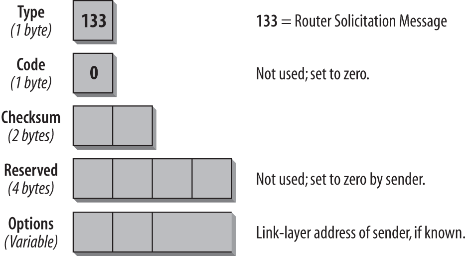
In the IP header of a Router Solicitation message, you will usually see the all-routers multicast address of ff02::2 as a Destination address. The hop limit is set to 255. The ICMP Type field is set to 133, which is the value for the Router Solicitation message. The Code field is unused and set to 0. The following two bytes are used for the Checksum. The next four bytes are unused and reserved for future use. The sender sets them to 0, and the receiver ignores those fields. For a Router Solicitation message, a valid option is the link-layer address of the sending host, if the address of the sending host is known. If the Source address on the IP layer is the unspecified (all-zeros) address, this field is not used. More options may be defined in future versions of ND. If a host cannot recognize an option, it should ignore the option and process the packet.
Routers that receive this Solicitation message reply with a Router Advertisement message. Routers also issue those messages periodically. The format of the Router Advertisement message is shown in Figure 4-11.
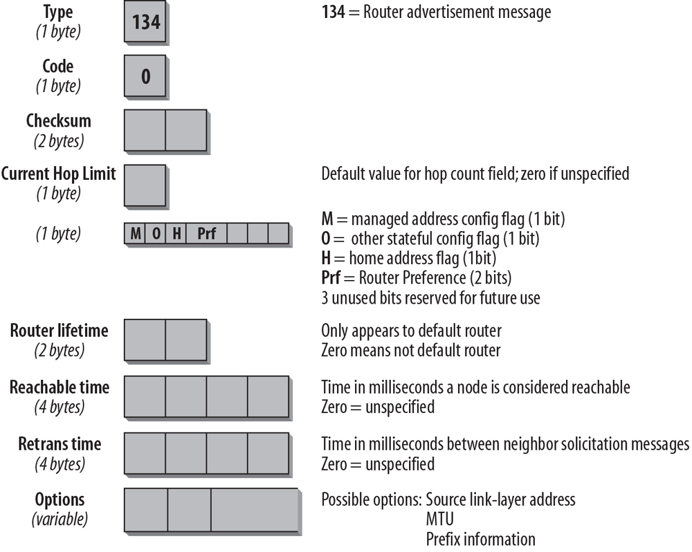
By inspecting the IP header of the Router Advertisement message, you can determine whether this Router Advertisement is periodic or was sent in reply to a Solicitation message. A periodic advertisementâs Destination address will be the all-nodes multicast address ff02::1. A solicited advertisementâs Destination address will be the address of the interface that originated the solicitation message. Again, the hop limit is set to 255.
The ICMP Type field is set to 134, the value for a Router Advertisement message; the Code field is unused and set to 0. The Current Hop Limit field can be used to configure all nodes on a link for a default hop limit. The value entered in this field will be used as a default hop limit value in outgoing packets by all nodes on the link. A value of 0 in this field means that this option is unspecified by this routerâin which case the default hop limit values of the source hosts are used.
The next 1-bit field, the M-Flag, specifies whether Stateful Configuration is to be used. Stateful Configuration refers to DHCPv6. If this bit is 0, the nodes on this link use Stateless Address Autoconfiguration (SLAAC). If the bit is set to 1, it specifies Stateful Autoconfiguration (DHCPv6). The O-Flag configures whether nodes on this link use DHCPv6 for other than IP address information. A value of 1 means the nodes on this link use DHCPv6 for nonaddress-related information. In this case a DHCPv6 client will send out a DHCPv6 information request message to obtain additional configuration options. The Mobile IPv6 specification (RFC 6275) defines the third bit, the Home Address flag (H-Flag). When a router sets the H-Flag to 1, it means that it is a home agent for this link.
Note that the DHCPv6 RFC leaves room for interpretation. It is possible that different operating systems have slightly different behavior in response to these two flags. There is a draft called âDHCPv6/SLAAC Address Configuration Interaction Problem Statement,â which describes these issues and discusses the results found with testing several desktop operating systems in a lab.
Note
For a discussion of Mobile IPv6 and Home Agent, refer to Chapter 8.
The next two bits are used by an optional extension to the Router Advertisement message, which allows routers to advertise preferences and more specific routes. This makes it possible for hosts to choose the best router in situations where they receive more than one router advertisement. It is also important for multihomed routers, which will be an increasingly important scenario in IPv6 networks. This extension uses the two bits after the H-Flag in the router advertisement as a Preference flag and defines a Route Information option. It is specified in RFC 4191. The remaining three bits of this byte are reserved for future use and must be 0.
The Router Lifetime field is important only if this router is to be used as a default router by the nodes on the link. A value of 0 indicates that this router is not a default router and will therefore not appear on the default router list of receiving nodes. Any other value in this field specifies the lifetime, in seconds, associated with this router as a default router. The maximum value is 18.2 hours.
The Reachable Time field indicates the time in which a host assumes that neighbors are reachable after having received a reachability confirmation. A value of 0 means that it is unspecified. The Neighbor Unreachability Detection algorithm uses this field.
The Retrans Timer field is used by the address resolution and Neighbor Unreachability Detection mechanisms; it states the time in milliseconds between retransmitted Neighbor Solicitation messages. A value of 0 indicates that this router is not configured with a retransmission timer.
For the Options field, there are currently three possible values:
- Source link-layer address.
- MTU size to be used on links with variable MTU sizes (Token Ring, for example).
- Prefix information, important for Stateless Address Autoconfiguration. The router inserts all its prefixes for the link that the nodes on the link need to know.
More options may be defined in future versions of ND. A trace file later in this chapter shows what the options look like.
Note
Router Advertisement spoofing is a security concern also known as rogue RA. The problem and mitigation techniques are discussed in the section Neighbor Discovery issues in Chapter 6 on Security.
Neighbor Solicitation and Neighbor Advertisement
This pair of messages fulfills two functions: the link-layer address resolution that is handled by ARP in IPv4, and the Neighbor Unreachability Detection mechanism. If the Destination address is a multicast address (usually the solicited node multicast address), the source is resolving a link-layer address. If the source is verifying the reachability of a neighbor, the Destination address is a unicast address. This message type is also used for Duplicate IP Address Detection (DAD).
The format of the Neighbor Solicitation message is shown in Figure 4-12.
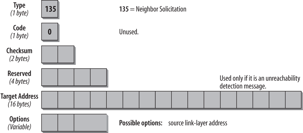
In the IP header of this message type, the Source address can be either the interface address of the originating host or, in the case of SLAAC and DAD, the unspecified (all-zeros) address. The hop limit is set to 255. The Type field in the ICMP header is set to 135, and the Code field is unused and set to 0. After the two checksum bytes, four unused bytes are reserved and must be set to 0. The target address is used in Neighbor Advertisement and Redirect messages. It must not be a multicast address.
The Options field can contain the link-layer Source address, but only if it is not sent from the all-zeros address. During Stateless Address Autoconfiguration, in a message that uses the unspecified address as a Source address, the Options field is set to 0. The link-layer option must be used in multicast solicitations (link-layer address detection) and can be used in unicast solicitations (Unreachability Detection).
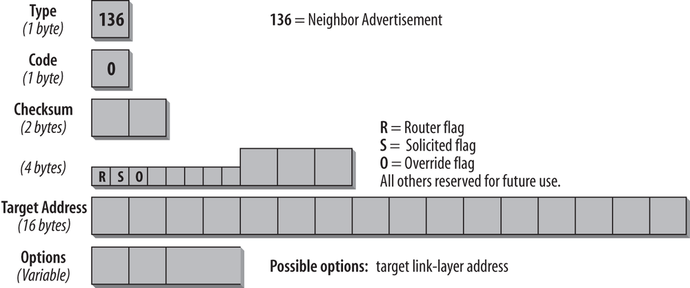
Neighbor Advertisement messages are sent as a reply to Neighbor Solicitation messages or to propagate new information quickly. The format of the message is shown in Figure 4-13.
The type of address in the IP header indicates whether the message is the answer to a solicitation or an unsolicited message. In the case of a solicited advertisement, the destination IP address is the Source address of the interface that sent the solicitation. If the message is the reply to a DAD message that originated from an unspecified Source address, the reply will go to the all-nodes multicast address of ff02::1. The same is true for all unsolicited periodic advertisements.
The Type field in the ICMP header is set to 136, the value for Neighbor Advertisement messages. The Code field is unused and set to 0. When the Router flag is set, the sender is a router.
When the Solicited flag is set, the message is sent in response to a Neighbor Solicitation. For instance, if a host confirms its reachability in answer to an unreachability detection message, the S-Bit is set. The S-Bit is not set in multicast advertisements. The Override flag indicates that the information in the Advertisement message should override existing Neighbor Cache entries and update any cached link-layer addresses. If the O-Bit is not set, the advertisement will not update a cached link-layer address, but it will update an existing Neighbor Cache entry for which no link-layer address exists. The O-Bit should not be set in an advertisement for an anycast address. I discuss the cache entries later in this chapter. The remaining 29 bits are reserved for future use and set to 0.
In solicited advertisements, the Target Address contains the address of the interface that sent the solicitation. In unsolicited advertisements, this field contains the address of the interface whose link-layer address has changed. A possible option for the Options field is the target link-layer address.
Table 4-6 helps you to identify what you are looking at and summarizes the different processes.
The ICMP Redirect Message
Routers issue ICMP Redirect messages to inform a node of a better first-hop node on the path to a given destination. A Redirect message can also inform a node that the destination used is in fact a neighbor on the same link and not a node on a remote subnet. The format of the ICMPv6 Redirect message is shown in Figure 4-14.
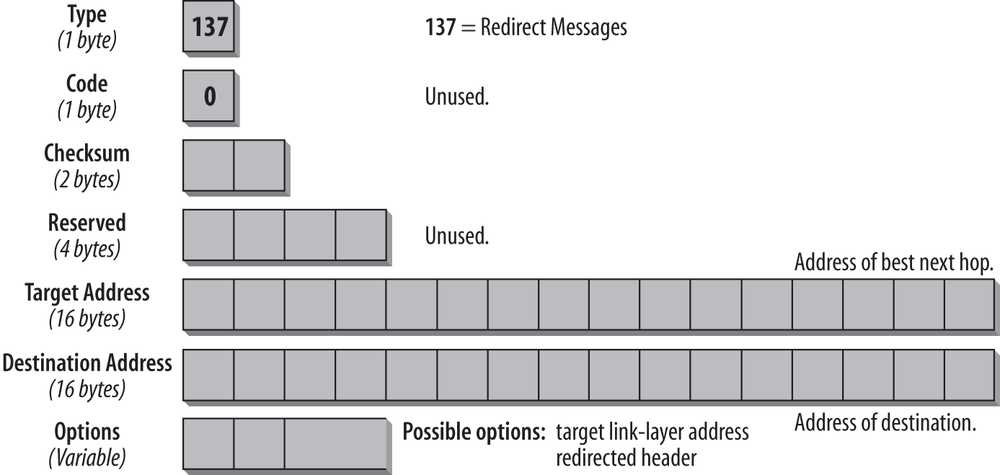
The Source address in the IP header must be the link-local address of the interface from which the message is sent. The Destination address in the IP header is the Source address from the packet that triggered the Redirect message. The hop limit is set to 255.
The Target Address field contains the link-local address of the interface that is a better next hop to use for the given Destination address. The Destination Address field contains the address of the destination that is redirected. If the address in the Target Address field is the same as the address in the Destination Address field, the destination is a neighbor and not a remote node. The Options field contains the link-layer address for the target (the best next-hop router) if it is known. This is an improvement on the IPv4 version, in which the host needed to issue a separate ARP request to determine the link-layer address of the next-hop router. The remaining bits in the Options field contain as much of the redirected header as fits into the minimum IPv6 MTU of 1,280 bytes.
Inverse Neighbor Discovery
Inverse Neighbor Discovery (IND) is an extension to ND. It was originally designed for Frame Relay networks, but it can be used in other networks with similar requirements. IND is specified in RFC 3122. It consists of two messages: the IND Solicitation and the IND Advertisement message. The messages are used to determine the IPv6 address of hosts for which the link layer address is known. IND corresponds to the Reverse Address Resolution Protocol (RARP) used with IPv4. The messages have the same format as the ND messages. The IND Solicitation has a message type of 141 and the IND Advertisement of 142. The code field is always set to 0.
The Options field has the same format as in the ND messages and contains the same options. Two new IND-specific options have been defined. Option type 9 defines the Source Address list; option type 10 the Target Address list (see the overview in Table 4-7).
- Source Address listâoption type 9
- List of one or more IPv6 addresses of the interface, which is specified in the Source link-layer address option.
- Target Address listâoption type 10
- List of all IPv6 addresses of the interface, which is specified in the Target link-layer address list.
When a host wants to determine the IPv6 address of an interface for which it knows the link-layer address, it sends an IND solicitation to the all-nodes multicast address. On the link layer, the message is sent directly to the interface in question. The destination replies with an IND advertisement containing the Target Address list. If the interface has more IPv6 addresses than fit into a single Advertisement message, it must send multiple IND advertisements. Like in all other ND messages, the hop limit is set to 255, and messages with a hop limit lower than 255 must be ignored.
Neighbor Discovery Options
Neighbor Discovery messages contain a variable-size Options field that has the format shown in Figure 4-15.
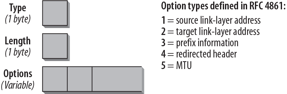
The Type field indicates what type of option follows. Table 4-7 shows an overview of the different options and the message types in which they are used.
The Length field indicates the length of the option. Value 0 is invalid for this field, and packets with this value must be discarded. The calculation of the length includes the Type and Length fields.
| Option type | RFC | Used in |
Type 1 Source link-layer address | RFC 4861 | Neighbor Solicitation Router Solicitation Router Advertisement IND Solicitation/Advertisement |
Type 2 Target link-layer address | RFC 4861 | Neighbor Advertisement Redirect IND Solicitation/Advertisement |
Type 3 Prefix | RFC 4861 | Router Advertisement |
Type 4 Redirected header | RFC 4861 | Redirect |
Type 5 MTU | RFC 4861 | Router Advertisement IND Solicitation/Advertisement |
Type 7 Advertisement interval | RFC 6275 | Router Advertisement (Mobile IPv6) |
Type 8 Home Agent information | RFC 6275 | Router Advertisement (Mobile IPv6) |
Type 9 Source address list | RFC 3122 | IND Solicitation |
Type 10 Target address list | RFC 3122 | IND Advertisement |
More options have been defined in other specifications, for instance a CGA option for Secure Neighbor Discovery (see below).
Note
For a full list of available options, refer to http://bit.ly/1na84cG.
Secure Neighbor Discovery
ND can be used for a number of attacks and should therefore be protected. An example of a Denial of Service attack is when a node on the link can both advertise itself as a default router and also send âforgedâ Router Advertisement messages that immediately time out all other default routers as well as all on-link prefixes.
The first protection is that packets coming from off-link (with a hop limit lower than 255) must be ignored. Further, the original ND specification suggests using IPsec to secure ND messages. However, this requires manual setup of security associations or the use of a key management protocol. The number of security associations to be configured for protecting ND can be very large, so this approach may be impractical.
The Secure Neighbor Discovery (SEND) working group was chartered with the goal to define the protocol support needed to secure ND. Three different trust models were outlined, roughly corresponding to secured corporate intranets, public wireless access networks, and pure ad hoc networks. A number of possible threats are discussed relating to these trust models. Refer to RFC 3756 for more details.
The SEND protocol, defined in RFC 3971 (updated by RFC 6494, RFC 6495, RFC 6980), is designed to counter the threats to ND. SEND can be used in environments where physical security on the link is not assured (such as over wireless) and attacks on ND are a concern. The following components are specified in RFC 3971:
- The authority of routers must be certified before it can be used as default router. A host must be configured with a trust anchor to which the router has a certification path. Certification Path Solicitation and Advertisement messages are used to discover a certification path to the trust anchor.
- Cryptographically Generated Addresses (CGAs) are used to make sure that the sender of a Neighbor Discovery message is the owner of the claimed address. A public-private key pair is generated by all nodes before they can claim an address. A new ND option, the CGA option, is used to carry the public key and associated parameters.
- Another new ND option, the RSA Signature option, is used to protect all messages relating to Neighbor and Router Discovery.
- Two new ND options, the Timestamp and Nonce options, have been introduced to prevent replay attacks.
The SEND protocol uses Cryptographically Generated Addresses. SEND currently does not support the protection of ND messages for nodes configured with a static address or with addresses configured through IPv6 Stateless Address Autoconfiguration mechanisms. All new option types and messages are specified in RFC 3971.
Cryptographically Generated Addresses (CGAs) are specified in RFC 3972 (updated by RFC 4581, RFC 4982), which defines a method for binding a public signature key to an IPv6 address in the SEND protocol. CGA are IPv6 addresses for which the interface identifier is generated by computing a cryptographic one-way hash function from a public key and auxiliary parameters.
Due to a lack of implementations by vendors, we donât expect SEND to be used widely. It does not make sense in a dual-stack environment, because IPv4 is not secured either. SEND would only make sense in an IPv6-only network.
Router Advertisement in the Trace File
At this point, you all deserve a refreshment. The following trace file shows what ND looks like in the real world and illustrates what we have been talking about.
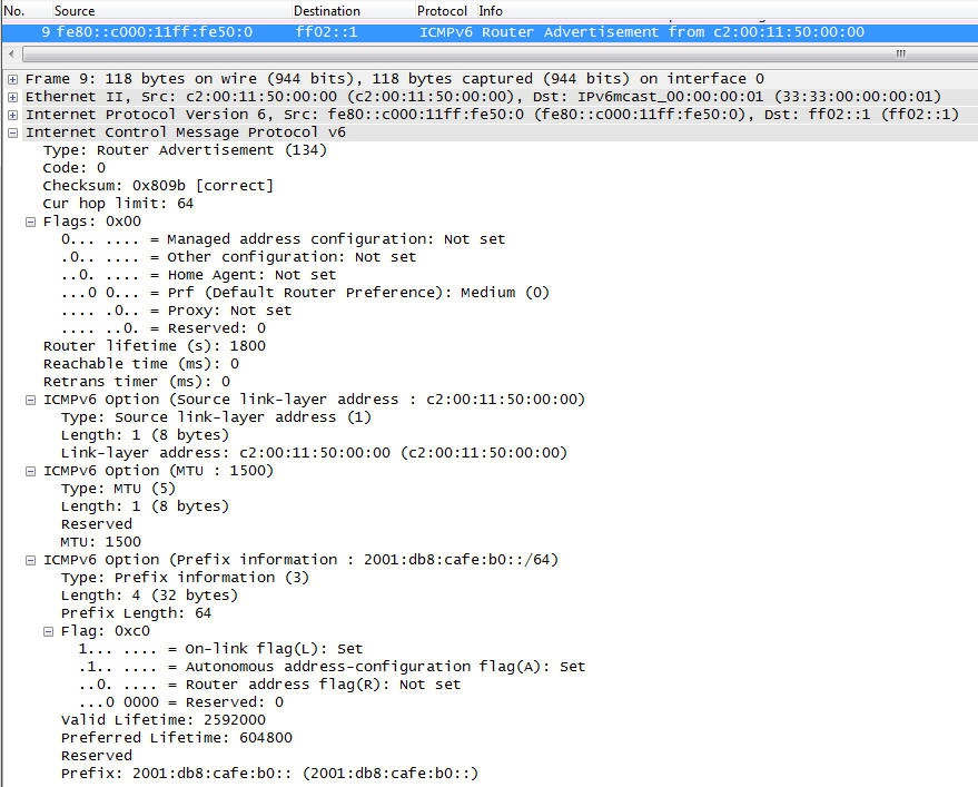
The screenshot in Figure 4-16 shows the details of a Router Advertisement with three Option fields. Besides initializing the IPv6 stack and configuring it for the prefix, we have not changed any of the default configuration parameters on the router. The options used in this case are options 1 (Source link-layer address), 5 (MTU size), and 3 (prefix information).
The Type field is set to 134, the value for a Router Advertisement. The Current Hop Limit has a value of 64. All nodes on this link will use this value for their Hop Count field. The M-Flag is set to 0, which means this interface will not use a DHCPv6 server to receive an IPv6 address. The O-Flag is also set to 0, which means the interface will not send out a DHCP information request to look for additional DHCP information (such as DNS or NTP servers). The Router Lifetime is set to 1,800, which indicates that this router is a default router. The first Option listed is type 1. The link-layer address in the detail screen contains the link-layer address of the router interface. The second option is of type 5, which can be used to change the MTU size from the default of 1,500 bytes (can be useful in some tunneling scenarios to prevent fragmentation of the tunneled packet). The third Option is of type 3 for prefix information. Note all the additional information that can be given with a prefix. The Prefix Length field specifies the number of bits valid for the prefix (i.e., the length of the subnet mask). The L-Bit is the on-link flag. If set, it indicates that this prefix can be used for on-link determination. If it is not set, the advertisement does not make a statement, and the prefix can be used for on- and off-link configuration. The A-Bit is the autonomous address configuration flag. If set, it indicates that the prefix can be used for autonomous address configuration. In this case, the host will generate an address by adding the interface identifier to the prefix or, if the privacy options are used, by adding a random number as an interface ID. The Valid Lifetime field specifies how long this prefix is valid (in milliseconds). The Preferred Lifetime specifies how long the address being configured with this prefix can remain in the preferred state (in milliseconds). The last field shows the prefix of 2001:db8: cafe:b0:: advertised by this router.
Draft-ietf-v6ops-dhcpv6-slaac-problem-00 describes how different operating systems have slightly different interpretations of the M-, O- and A-Flag. The reason for the ambiguity comes from the fact that the specification defines these flags not as prescriptive, but rather as advisory. Therefore different operating systems take different approaches of how to interpret these flags. The RFC reviews the standard definition of the flags, and provides a test result of several major desktop operating systemsâ behavior.
Link-Layer Address Resolution
Link-Layer Address Resolution is the process that happens when a node wants to determine the link-layer address of an interface for which it knows the IP address. With IPv4, this is the functionality of ARP. Link-Layer Address Resolution is performed only for nodes that are known to be on the same link (neighbors) and is never performed for multicast addresses.
With IPv6, this is a functionality accomplished with ND messages. A node wanting to resolve a link-layer address sends a Neighbor Solicitation message to the solicited node multicast address of the neighbor. This solicitation message contains the link-layer address of the sender in the ND option field. If the destination is reachable, it replies with a Neighbor Advertisement message containing its link-layer address. If the resolving node does not receive an answer within a preconfigured number of attempts, the address resolution has failed.
Neighbor Unreachability Detection
A neighbor is considered reachable if the node has recently received a confirmation that packets sent to the neighbor have been received by its IP layer. This confirmation can come in one of two ways: it can be a Neighbor Advertisement in response to a Neighbor Solicitation, or it can be an upper-layer process that indicates the successful connection (e.g., an active TCP connection). In this case, the receipt of TCP acknowledgments implies the reachability of the neighbor.
To keep track of active and reachable connections, IPv6 nodes use different tables. Two important tables relating to ND are the Neighbor and Destination caches, which I discuss in the next section.
Neighbor Cache and Destination Cache
IPv6 nodes need to maintain different tables of information. Among these tables, the Neighbor Cache and Destination Cache are particularly important. Depending on the IPv6 stack you are working with, the implementation and the troubleshooting utilities will be different. But the information must be available on every IPv6 node.
- Neighbor Cache
- The Neighbor Cache maintains a list of neighbors to which traffic has been sent recently. They are listed by their unicast IP addresses, and each entry contains information about the neighborâs link-layer address and a flag that indicates whether the neighbor is a router or host. This can be compared to the ARP cache in an IPv4 node. The entry also contains information about whether there are packets queued to be sent to that destination, information about the neighborâs reachability, and the time the next neighbor unreachability detection event is scheduled to take place.
- Destination Cache
- This table maintains information about destinations to which traffic has been sent recently, including local and remote destinations. The Neighbor Cache can be seen as a subset of Destination Cache information. In case of remote destinations, the entry lists the link-layer address of the next-hop router. The Destination Cache is updated with information received by ICMP Redirect messages. It can also contain additional information about MTU sizes and round-trip timers.
The Neighbor and Destination Caches have been mentioned in regard to the Override flag that can be set in a Neighbor Advertisement message. If the Override flag is set, the information in the Advertisement message should override existing Neighbor Cache entries and update any cached link-layer addresses in the cache of the host that receives the advertisement. If the O-Bit is not set, the advertisement will not update a cached link-layer address, but it will update an existing Neighbor Cache entry for which no link-layer address exists.
The screenshot in Figure 4-17 shows the Neighbor Cache entries of our router. There were two hosts on the link at the time the screenshot was taken.
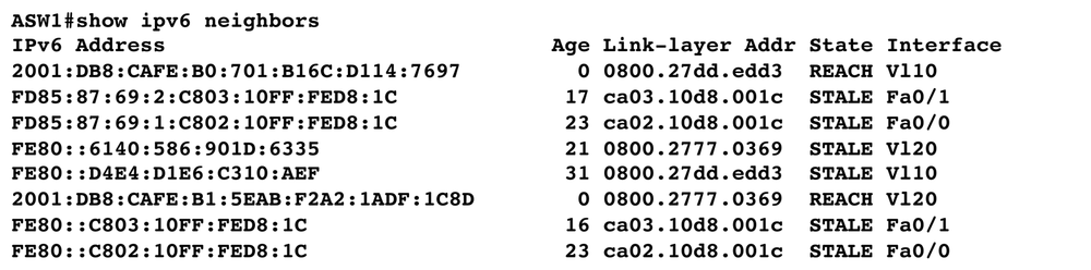
According to RFC 4861, a Neighbor Cache entry can be in one of five states. The five states are explained in Table 4-8.
If you are interested in the details about the timers, default values, and configuration options, refer to RFC 4861.
Neighbor Discovery and Fragmentation
As will be discussed in Chapter 6 on Security, ND-based attacks can be mitigated by implementing RA Guard. With RA Guard you can filter ND messages based on Layer 2 source and filtering rules. It has been found that fragmentation on Neighbor Discovery messages can pose a security risk, due to the fact that the fragmentation header can make it impossible for Layer 2 devices to properly filter ND messages. RFC 6980, âSecurity Implications of IPv6 Fragmentation with IPv6 Neighbor Discovery,â explains the problem and specifies that all ND and SEND messages must not use fragmentation.
Note
Refer to Chapter 6 for more information on RA Guard and First Hop Security.
Stateless Address Autoconfiguration (SLAAC)
The autoconfiguration capability of IPv6 saves network administrators a lot of work. It has been designed to ensure that manually configuring hosts before connecting them to the network is not required. Even larger sites with multiple networks and routers should not need a DHCP server to configure hosts. The autoconfiguration features of IPv6 will be a key feature of the protocol when all sorts of devicesâsuch as televisions, refrigerators, DVD players, and mobile phonesâuse IP addresses. You donât want to depend on a DHCP server to use your home devices. It is also useful in public ad hoc networks to minimize administration. In an enterprise scenario we rather expect DHCPv6 to be used, mainly for traceability purposes.
Note
DHCPv6 is discussed in Chapter 5.
IPv6 knows Stateless and Stateful Address Autoconfiguration. Stateful Address Autoconfiguration is DHCPv6. Whatâs really new with IPv6 is that hosts can autoconfigure their IPv6 addresses without any manual configuration of the host. Some configuration might be done on the routers, but no DHCP servers are required for this configuration mechanism. To generate its IP address, a host uses a combination of local information, such as an interface ID based on its MAC address or a randomly chosen interface ID, and information received from routers. Routers can advertise one or multiple prefixes, and hosts determine prefix information from these advertisements. This also allows for simpler renumbering of a site: only the prefix information on the router has to be changed. For instance, if you change your ISP and the new ISP assigns a new IPv6 prefix, you can configure your routers to advertise this new prefix, keeping the subnet IDs that you used with the old prefix. All hosts attached to those routers will renumber themselves through the autoconfiguration mechanism. You can find more on renumbering networks later in this chapter. If there is no router present, a host can generate only a link-local address with the prefix fe80. With this address only nodes on the link can be reached.
Stateless and Stateful Address Autoconfiguration can also be combined. For instance, a host can use Stateless Address Autoconfiguration to generate an IPv6 address but then use DHCPv6 for additional parameters. To configure hosts that use SLAAC for additional information (e.g., DNS servers), a Stateless DHCP server has been specified.
An IPv6 address is leased to a node for a certain lifetime. When the lifetime expires, the address becomes invalid. To make sure an address is unique on a link, a node runs the Duplicate Address Detection (DAD) process. The DAD algorithm is defined in RFC 4862. An IPv6 address can have different states:
- Tentative address
- This is an address that has not yet been assigned. It is the state prior to the assignment, when uniqueness is being verified (during DAD). A node cannot communicate in the network using a tentative address. The only messages that can be processed with a tentative address are ND messages relating to the autoconfiguration process.
- Preferred address
- This is an address that has been assigned to an interface and can be used without any restrictions for the lifetime assigned.
- Deprecated address
- The use of this address is discouraged but not forbidden. A deprecated address might be one whose lifetime is about to expire. It can still be used to continue a communication that would disrupt a service if the address changed. It is no longer used as a Source address for newly established communications.
- Valid address
- This term is used for both the Preferred and Deprecated address.
- Invalid address
- An invalid address is not assigned to an interface. A valid address becomes invalid when its lifetime expires.
- Optimistic address
- An address that is assigned to an interface and available for use, subject to restrictions, while the DAD process has not completed yet. This address state is introduced in RFC 4429, âOptimistic Duplicate Address Detection (DAD) for IPv6.â Optimistic Duplicate Address Detection (DAD) is a modification of the existing ND and SLAAC processes. The intention is to minimize address configuration delays in the successful case, and to reduce disruption as far as possible in the failure case.
Note
Autoconfiguration as defined in RFC 4862 only applies to hosts, not to routers. Routers should be configured in a different way. A router can use Stateless Autoconfiguration for the generation of its link-local addresses, and it must use the DAD process for each of its addresses.
When a node is autoconfigured, the following steps are performed:
-
A link-local address is generated by using the link-local prefix of
fe80and appending the interface identifier. This address is a tentative address. -
The node joins the following multicast groups: the all-nodes multicast group (
ff02::1) and the solicited-node multicast group for the tentative address (from step 1). - A Neighbor Solicitation message is sent out with the tentative address as the target address. The IP Source address of this message is the all-zeros address; the IP Destination address is the solicited-node multicast address. This is the DAD process to detect whether another node on the link already uses this address. If there is such a node, it replies with a Neighbor Advertisement message, and the autoconfiguration mechanism stops if the interface ID is an EUI-64 ID. If the interface ID is a randomized number, new combinations will be tested. How this is done in detail depends on the operating system used. If the process stops, manual reconfiguration of the host is required. If there is no answer to the Neighbor Solicitation, it is safe to use the address; the address is assigned to the interface and the state of the address changes to preferred. IP connectivity on the local link is now established. So far, the process is the same for hosts and routers, but only hosts perform the next step.
-
In order to determine if there are IPv6 routers out there, to find a default gateway, and if there is a prefix to use for SLAAC, the host sends a Router Solicitation message to the all-routers multicast group of
ff02::2. - All routers on the link reply with a Router Advertisement. For each prefix in Router Advertisements with the Autonomous Configuration flag set, the node generates an address, combining the prefix with the interface identifier. These addresses are added to the list of assigned addresses for the interface.
All addresses must be verified with a Neighbor Solicitation message (DAD) before they are assigned. If the link-local address was generated through the autoconfiguration mechanism using the interface identifier, uniqueness has been verified in step 3 and may not need to be repeated for additional addresses that use the same interface identifier. All other addresses configured manually or through Stateful configuration need to be verified individually. Multihomed hosts perform autoconfiguration for each interface.
So we have two types of addresses based on how the interface ID is generated:
- Permanent IPv6 address
- This is a Global Unicast or ULA address assigned to the interface either via autoconfiguration (SLAAC or DHCPv6) or manually. It does not change as long as the interface is enabled and active.
- Temporary IPv6 address
- This is a Global Unicast or ULA address assigned to the interface that uses a random interface ID that has a limited lifetime and changes in regular and configurable intervals.
Note
All the different address types mentioned in these descriptions are discussed in Chapter 2.
The trace shown in the screenshot in Figure 4-18 was taken during the autoconfiguration process of our Windows 8 host. The figure shows some of the processes and message types discussed earlier, and the discussion of the trace summarizes the concepts in this section.
As long as the booting host does not have a valid IPv6 address, it sends all packets from its unspecified all-zeros address, represented as :: in the trace file.
- Packet 1
-
In this first packet, the booting host (interface) sends a Neighbor Solicitation from the all-zeros address to the solicited node address in order to perform DAD. The Target Address field of the ICMPv6 header contains the link-local address of
fe80::d4e4:d1e6:c310:aef. If another node on the link already used this address, it would reply with a Neighbor Advertisement message. - Packet 2
-
With the second packet, it sends a Router Solicitation message (message type 133) to the all-routers multicast address
ff02::2. - Packet 3
-
With this packet, the host registers for the solicited node multicast address of
ff02::1:ff10:aef.The packet contains a Hop-by-Hop Options header with option type 5 for MLD messages. The hop limit is set to 1. - Packet 4
-
The router sends a Router Advertisement (RA) to the all-nodes multicast address of
ff02::1, because the host does not have a valid preferred IPv6 address yet. With this RA the router advertises itself as default gateway (router lifetime set to 1,800 seconds). This RA has the M- and O-Bit set to zero (no DHCPv6) and the Autonomous Address Configuration flag set to one. The prefix option contains the prefix2001:db8:cafe:b0::/64. The details of this RA can be seen in Figure 4-16. - Packet 5
-
With this packet, the host registers for the solicited node multicast address of
ff02::1:ff1c:4c99. The packet contains a Hop-by-Hop Options header with option type 5 for MLD messages. The hop limit is set to 1. - Packet 6 and 7
-
The host performs the DAD test for the addresses formed by combining the global prefix received in the Router Advertisement (packet four) with the two interface IDs. The address with the interface ID ending in
aefis the permanent address. The address with the interface ID ending in4c99is the address using the privacy option, or as Microsoft calls it, the temporary address. The packet is sent from the all-zeros address to the respective solicited node multicast address. The IPv6 address can be seen in the summary line of packet 6 and 7. - Packet 8
- With this packet, the host registers for its two solicited node multicast addresses. The packet contains the Hop-by-Hop Options header with option type 5 for MLD messages.
- Packet 9, 10, and 11
-
With these three packets the host advertises itself on the link for the following addresses: the link-local of
fe80::d4e4:d1e6:c310:aef, for the global address2001:db8:cafe:b0:d4e4:d1e6:c310:aef, and also for the global address with the temporary IID2001:db8:cafe:b0:a43d:d55b:d1c:4c99. The override flag is set in all three packets, which tells the receivers to update their neighbor cache. For communication going out to the Internet, this node should use the temporary global address ending in4c99.
When you take your own traces to analyze a boot process and use different operating systems, you will also find differences in the process shown in the trace file. The differences come from the fact that the RFCs leave room for interpretation of the standard, which can be implemented slightly differently by different vendors. As long as the âMUSTâ rules in the RFCs are followed, compliance should not be an issue. Note the âshouldâ; this is where your trace file analysis expertise will be helpful in case of failures. Another reason for differences is that the implementation behavior depends on what level and state of the standardization has been implemented. If one operating system has an implementation of the privacy option, this stack will obviously behave differently from a stack that has not implemented the privacy option. So when you analyze processes of a specific operating system, get enough information from the vendor about which RFCs have been implemented. And if the vendor states that it implemented something, you can use your trace files to verify whether the stack works as it is supposed to.
So for instance, with regard to DAD and how Microsoft has implemented it, Windows skips the DAD process for temporary addresses since the interface ID is randomly generated. It will start using the temporary address right away and do a DAD process later to confirm the address is not in use. This is the Opportunistic DAD process mentioned earlier. Also note that on Microsoft operating systems, the default behavior is different on a client OS such as Windows 7 or 8 and a Windows server OS such as Windows 2008 or higher. The server operating systems do not enable the temporary addresses by default. Refer to Microsoftâs documentation for more information.
Until recently, the choice for interface IDs with SLAAC was either hardware-based (EUI-64) or randomized and temporary (Privacy addresses). RFC 7217, âA Method for Generating Semantically Opaque Interface Identifiers with IPv6 Stateless Address Autoconfiguration (SLAAC),â defines stable randomized interface IDs. As the name implies they are stable but not based on the Layer 2 address.
Note
For those of you who use and manage Microsoft operating systems, there is a great book which I recommend highly. It is written by Ed Horley and will save you a lot of sleepless nights and troubleshooting hours. The title is Practical IPv6 for Windows Administrators (Apress).
Network Renumbering
Renumbering a network means replacing an old prefix with a new prefix. This can become necessary for a number of reasons, a common one being a change of provider, which usually implies a change of prefix. Moving from the IPv4 world to the IPv6 world, prefixes and addresses become more and more flexible and are not uniquely identifying a network or hosts. The IPv6 addressing architecture adds the concept of interfaces having multiple addresses. This challenges us to develop new addressing concepts.
With the mechanisms given by ICMPv6, renumbering a network in an IPv6 world may become a lot easier in the future. It is a procedure that should be considered during creation of an IPv6 address plan. Currently there is not much operational experience.
Renumbering a network may encompass the following steps:
- Each link in the network must be assigned a subprefix from the new prefix before beginning the procedure. This is important for the overall process, in order to ensure proper configuration of all relevant devices and services such as routers, switches, interfaces, DNS, DHCP, etc.
- The DNS database must be updated with the addresses for interfaces from the new prefix, and addresses for interfaces from the old prefix must be removed. Obviously the changes to DNS must be coordinated with the changes to addresses assigned to interfaces. The propagation of this new information can be controlled by parameters such as the Time to Live (TTL) for DNS records and the update interval between primary and secondary DNS servers.
- Switches and routers are prepared for the new prefix. All necessary changes in the routing infrastructure for the new prefix are added in parallel to the old prefix, while the old prefix is still used for datagram services. This includes not only routers and switches, but also firewalls, ingress and egress filters, and all other filtering functions. For propagating subnet prefix information to routers, the IPv6 Prefix option for DHCPv6 (RFC 3633) may be used. In the case where hosts use Stateless Address Autoconfiguration, the routers are not configured to advertise the prefix for autoconfiguration yet (meaning that the Autonomous Address Configuration flag is not set). This will be done once stable routing for the new prefix has been verified.
- All access lists, route maps, and other network configuration options (e.g., name services other than DNS) that use IP addresses should be checked to ensure that hosts and services that use the new prefix will behave as they did with the old one.
- Test and verify network infrastructure and routing for the new prefix.
- Advertise the new prefix outside of the corporate network. Configure all border defense systems accordingly to protect the new prefix from outside attacks.
- Assign addresses from the new prefix to interfaces on hosts while still retaining the addresses from the old prefix. If Stateless Autoconfiguration is used, the autonomous address-config flag is set for the new prefix, so hosts configure addresses for the new prefix in addition to the old addresses. DHCP now assigns addresses from both prefixes if it is used. The new information can be propagated by using the DHCP Reconfigure message, which will cause every DHCP client to contact the DHCP server. The addresses from the new prefix will not be used until they are inserted into DNS.
- When the new prefix has been fully integrated into the network infrastructure and tested for stable operation, hosts, switches, and routers can begin using the new prefix. Once the transition has completed, the old prefix will not be in use in the network and can be removed step by step from DNS.
Special attention has to be given to applications and devices that do not get their IP addresses from DHCP or DNS, or that cache or store IP address information locally.
This is a high-level view of a renumbering process and obviouslyâas all network administrators know wellâthere are many details and possible pitfalls to be considered. Thorough and careful planning of this process is a must. RFC 4192 describes this process. RFC 7010, âIPv6 Site Renumbering Gap Analysis,â which provides a good overview and an update to RFC 4192, discusses currently available mechanisms and components to support renumbering and analyzes gaps and mechanisms that should be developed in order to make renumbering an easier process.
There is a specification for IPv6-to-IPv6 Network Prefix Translation (NPTv6, RFC 6296) that can also be used in the scenario of changing prefixes due to ISP changes. This sort of introduces NAT for IPv6, although not with the issues of port translation, because in IPv6 this would be a one-to-one mapping from an address perspective.
Note
Refer to Chapter 7 for a discussion of NPTv6.
Path MTU Discovery
With IPv4, every router can fragment packets if needed. If a router cannot forward a packet because the MTU of the next link is smaller than the packet it has to send, the router fragments the packet. It cuts it into slices that fit the smaller MTU and sends it out as a set of fragments. The packet is then reassembled at the final destination. Depending on the network design, an IPv4 packet may be fragmented more than once during its travel through the network.
With IPv6, routers do not fragment packets anymore; the sender takes care of it. Path MTU Discovery tries to ensure that a packet is sent using the largest possible size that is supported on a certain route. The Path MTU is the smallest link MTU of all links between a source and a destination. The discovery of the Path MTU is described in RFC 1981.
The discovery process works like this. First, a host assumes that the Path MTU is the same as the MTU of the first hop link and it uses that size. If the packet is too big for a certain router along the path to deliver the packet to the next link, the router discards the packet and sends back an ICMPv6 Packet Too Big message. Recall that this message type includes the MTU size of the next hop link. The host now uses this MTU for sending further packets to the same destination. The host will never go below the IPv6 minimum MTU size of 1,280 bytes, however. The process of receiving a Packet Too Big message and reducing the size of the packets can happen more than once before the packet reaches its destination. The discovery process ends when the packets arrive at the final destination.
Note
Note that ICMPv6 Packet Too Big messages should not be blocked, as this will make fragmentation fail.
The path from a given source to a given destination can change, and so can the Path MTU. Smaller MTU sizes are discovered by getting Packet Too Big messages. An IPv6 host will try to increase the MTU size from time to time in order to be able to detect a larger Path MTU. Path MTU Discovery also supports multicast destinations. If the destination is multicast, there are many paths that copies of the packets may travel, and each path can have a different Path MTU. Packet Too Big messages will be generated just as with a unicast destination, and the packet size used by the sender is the smallest Path MTU of the whole set of destinations.
Multicast Listener Discovery
Multicast has been available in IPv4 since 1988 and is used to address a certain group of hosts at the same time. Instead of sending out a broadcast, which is not routable and has to be processed by every node on the subnet, the multicast packet is addressed to a multicast group address out of the Class D address range. Only the hosts that are members of that multicast group will process the packet. Multicast messages can be forwarded over routers. In order to make this routing efficient, a multicast group management protocol ensures that routers only forward multicast packets over interfaces to links with members of the multicast group.
In IPv6, multicast is an integral part of the protocol and is available on all IPv6 nodes. A new multicast address format has been defined with a prefix of ff and with added functionality by using scopes in addition to the group address. For example, a multicast group address can be in a link-local scope (ff02), a site-local scope (ff05), or a global scope (ff0e).
Note
For an explanation of the multicast address format and a list of scope identifiers, refer to Chapter 2.
Multicast group management in IPv4 is done through Internet Group Management Protocol (IGMP). Version 2 of IGMP is defined in RFC 2236. IPv6 uses ICMPv6 messages for the same functionality; initial development was based on the IGMPv2 specification. It is now called Multicast Listener Discovery (MLD). Version 1 of MLD is defined in RFC 2710 (updated by RFC 3590 and RFC 3810). In 2004, MLD version 2 was defined. It extends MLD version 1 to support the use of Source-Specific Multicast (SSM). It is based on IGMPv3 (RFC 3376) and is specified in RFC 3810 and RFC 4604. MLDv2 is compatible with MLD version 1.
MLD is the protocol that allows multicast listeners to register for multicast addresses they want to use, to ensure efficient routing. Therefore, a routing mechanism is needed to manage the forwarding of multicast messages. PIM (Protocol Independent Multicast, RFC 4601) can be used with IPv6 with minimal changes.
Note
To find information about the status of PIM, go to the IETF working group at http://www.ietf.org/html.charters/pim-charter.html.
MLD is an asymmetric protocol. The behavior of listeners, i.e., nodes that want to receive messages destined for a specific multicast group, differs from the behavior of routers. For multicast addresses where a router is a listener, it uses both parts of the protocol. Routers use MLD to discover which multicast addresses have listeners on each of their links. For each attached link, the router keeps a list of listener addresses. It does not keep track of how many members are listening to an address. A multicast address is listed as long as there is at least one member on the link. A listener sends member reports for its multicast addresses. With these messages, it registers with routers on the link to receive the messages addressed to the respective multicast group. If the multicast address is not in the routerâs list for this link, the router adds the address to its list of multicast addresses to be forwarded over this interface. With a Done message, a listener deregisters for a multicast address. When the last member of a group deregisters for a multicast address, the router removes the address from its list for this link.
All MLD messages are sent with a link-local IPv6 Source address and a hop limit of one to make sure they remain on the local link. The packet has a Hop-by-Hop Options header with the Router Alert flag set. Thus, routers will not ignore the packet, even if they are not listening to the multicast group address in question. Refer to Chapter 2 for more information on Extension headers.
MLDv1
The following message types have been specified for MLDv1 (RFC 2710):
- Multicast Listener Queryâtype 130
- Used by an IPv6 router to query the multicast addresses on a link. There are two types of queries: the general query used to determine the multicast addresses that have listeners on the link (in the general query, the multicast address field is set to zero) and the address-specific query used to find out whether there are members for a specific multicast address on a link (the multicast address field is set to the multicast address for which the query is done).
- Multicast Listener Reportâtype 131
- Used by a listener to register for a multicast group. This can be an unsolicited registration or the answer to a multicast listener query from the router.
- Multicast Listener Doneâtype 132
- Sent by a listener to deregister for a multicast address. When a router receives a Multicast Listener Done message from the last member of the multicast address on a link, it will delete the multicast address from its list of multicast addresses to be forwarded over this interface.
All three message types of MLDv1 have the same format, which is shown in Figure 4-19.

The Type field is 130 for Multicast Listener Queries, 131 for Multicast Listener Reports, or 132 for Multicast Listener Done messages. The Code field is set to 0 by the sender and ignored by the receiver. The Maximum Response Delay field is used only in query messages. This is the maximum allowed delay (in milliseconds) in which a node has to send a report if it has a listener. In all other messages, this field is set to 0. The Multicast Address field is set to 0 in a general query. In an address-specific query, it contains the multicast group address to be queried. In Report and Done messages, this field contains either the multicast group to which a member listens (Report message) or the group it is leaving (Done message).
Routers send general queries to the link-local scope all-nodes multicast address ff02::1. Any station that wants to send a report in answer to a query starts a timer when it receives the query and is supposed to wait some random delay before sending the report. The maximum delay is the one specified in the Maximum Response Delay field in the query. If the station sees another station sending a report within that delay, it stops the process. Thus, multiple reports for the same address can be avoided. Group membership join reports and terminations are sent to the address in question.
The link-local scope all-nodes address (ff02::1) is a special address. It never sends a membership Report or a Done message. If an address has a scope of 1 (interface-local), MLD messages are never sent. Table 4-9 summarizes the message types and their Destination address.
| Message type | IPv6 Destination address |
General Query | Link-local scope all-nodes ( |
Multicast Address-Specific Query | The multicast address being queried |
Report | The multicast address being reported |
Done | Link-local scope all-routers ( |
RFC 2710 contains a lot of interesting and detailed information. It discusses various states that nodes can go through and includes state transition diagrams. There is also much detailed information on timers: how they are used, their default values, and how they can be configured.
MLDv2
MLD version 2 has been specified in RFC 3810 and RFC 4604. It is based on IGMPv3 (RFC 3376). MLDv2 adds the ability for a node to do source filtering, which means to report interest in listening to packets with a particular multicast address from only specific Source addresses or from all sources except for specific Source addresses. This is also referred to as Source-Specific Multicast (SSM) as opposed to Any Source Multicast (ASM), which is the name for the previous version, based on IGMPv2 (MLDv1).
The filter mode to support SSM may be either INCLUDE or EXCLUDE. In INCLUDE mode, reception of packets sent to the specified multicast address is enabled only from the source addresses listed in the source list. In EXCLUDE mode, reception of packets sent to the given multicast address is enabled from all source addresses except those listed in the source list.
There are two message types for MLDv2:
- Multicast Listener Queryâtype 130
- Version 2 Multicast Listener Reportâtype 143 (RFC 3810)
To be interoperable with MLDv1, MLDv2 implementations also need to support Version 1 Multicast Listener Report (type 131) and Version 1 Multicast Listener Done (type 132) messages.
For MLDv2 query messages, the MLD header is extended with the following fields, which are appended after the Multicast Address field shown in Figure 4-19:
- Reservedâ4 bits
- Must be set to zero.
- S-Flag (Suppress Router-Side Processing)â1 bit
- When set to one, the S-Flag indicates to any receiving multicast routers that they have to suppress the normal timer updates they perform upon hearing a Query.
- QRV (Querierâs Robustness Variable)â3 bits
- If nonzero, the QRV field contains the Robustness Variable value used by the Querier. This value affects timers and the number of retries. Included in queries in order to synchronize all MLDv2 routers connected to the same link.
- QQIC (Querierâs Query Interval Code)â8 bits
- The Querierâs Query Interval Code field specifies the Query Interval used by the Querier. Included in queries in order to synchronize all MLDv2 routers connected to the same link.
- Number of Sourcesâ16 bits
- The Number of Sources (N) field specifies how many Source addresses are present in the Query. This number is zero in a General Query or a Multicast Address Specific Query, and nonzero in a Multicast Address and Source Specific Query.
- Source Addressâvariable length
- Contains the Source addresses. Length is defined by the number of addresses specified in the N-Field.
There are three different kinds of queries that can be sent:
- General Query
- Sent by the Querier to learn which multicast addresses have listeners on an attached link. In a General Query, both the multicast address field and the number of sources field are set to zero.
- Multicast Address Specific Query
- Sent by the Querier to learn if a particular multicast address has any listeners on an attached link. In a Multicast Address Specific Query, the Multicast Address field contains the multicast address of interest, while the Number of Sources field is set to zero.
- Multicast Address and Source Specific Query
- Sent by the Querier to learn if any of the sources from the specified list for the particular multicast address has any listeners on an attached link or not. In a Multicast Address and Source Specific Query, the Multicast Address field contains the multicast address of interest, while the Source Address field(s) contain(s) the source address(es) of interest.
And Figure 4-20 shows what these fields look like in a trace file.
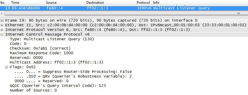
This is a Multicast Address Specific Query, as it contains the multicast address to be checked (ff02::1:3) in the Multicast Address field. The Number of Sources field is set to zero. What you canât see in this screenshot is that the message has a Hop-by-Hop Options header with a Router Alert Option.
MLDv2 Listener Report messages have the following format:
- Type fieldâ1 byte, set to 143
- Reservedâ1 byte
- Checksumâ2 bytes
- Reservedâ2 bytes
- M-Field (Number of Multicast Address Records)â2 bytes
- Multicast Address Recordsâvariable length, depending on number of addresses
Figure 4-21 shows the MLDv2 Listener Report in the trace file.
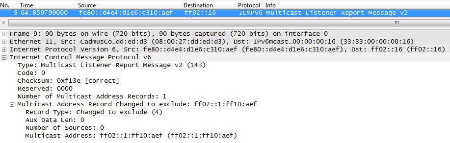
In this case, there is only one multicast address record, so the value is set to one. Each Multicast Address Record is a block of fields that contain information on the MLD sender listening to a single multicast address on the interface from which the Report is sent. It includes a field specifying the number of sources and the list of sources for a particular multicast address. The Record Type field specifies the type of the Multicast Address Record described next.
A node that receives a Query on an interface responds with a Current State Record to report the state of the interface regarding the multicast address in question. The Current State Record can have one of two values:
- Value 1âMODE_IS_INCLUDE
- Indicates that the interface has a filter mode of INCLUDE for the specified multicast address.
- Value 2âMODE_IS_EXCLUDE
- Indicates that the interface has a filter mode of EXCLUDE for the specified multicast address.
If there is a change of the filter mode, a node sends a Filter Mode Change Record. This record is included in a report sent from the interface where the change occurred. The Filter Mode Change Record can have one of two values:
- Value 3âCHANGE_TO_INCLUDE_MODE
- Indicates that the interface has changed to INCLUDE filter mode for the specified multicast address. The Source Address fields in this Multicast Address Record contain the interfaceâs new source list for the specified multicast address, if it is nonempty.
- Value 4âCHANGE_TO_EXCLUDE_MODE
- Indicates that the interface has changed to EXCLUDE filter mode for the specified multicast address. The Source Address fields in this Multicast Address Record contain the interfaceâs new source list for the specified multicast address, if it is nonempty.
If there is a change of source list, a node includes a Source List Change Record in a report sent from the interface where the change occurred. The Source List Change Record can have one of two values:
- Value 5âALLOW_NEW_SOURCES
- Indicates that the Source Address fields in this Multicast Address Record contain a list of the additional sources that the node wishes to listen to for packets sent to the specified multicast address. If the change was to an INCLUDE source list, these are the addresses that were added to the list; if the change was to an EXCLUDE source list, these are the addresses that were deleted from the list.
- Value 6âBLOCK_OLD_SOURCES
- Indicates that the Source Address fields in this Multicast Address Record contain a list of the sources that the node no longer wishes to listen to for packets sent to the specified multicast address. If the change was to an INCLUDE source list, these are the addresses that were deleted from the list; if the change was to an EXCLUDE source list, these are the addresses that were added to the list.
Version 2 Multicast Listener Reports are sent with an IP Destination address of ff02::16. All MLDv2-capable multicast routers listen to this address.
Note
For more information about Multicast and Anycast Group Membership, refer to the IETF Magma Group at http://bit.ly/1rIgD3q.
Multicast Router Discovery
Multicast Router Discovery (MRD) is a general mechanism that allows for the discovery of multicast routers. It does not depend on a specific multicast routing protocol. It is specified in RFC 4286 and introduces three new message types:
- Multicast Router Advertisement (message type 151)
-
This message is sent by routers to advertise that IP multicast forwarding is enabled. It is sent from a link-local Source address to the all-snoopers multicast address (
ff02::6a). - Multicast Router Solicitation (message type 152)
-
This message is sent by devices in order to solicit Advertisement messages from multicast routers. It is sent from a link-local Source address to the all-routers multicast address (
ff02::2). - Multicast Router Termination (message type 153)
-
This message is sent by routers to advertise that it stops IP multicast routing functions on an interface. It is sent from a link-local Source address to the all-snoopers multicast address (
ff02::6a).
All MRD messages are sent with an IPv6 Hop Limit of 1 and contain the Router Alert Option.
Now that you know how all the cool functionality of IPv6 works, the next chapter discusses networking aspects such as Layer 2, Routing, Multicast, QoS, DHCPv6, and DNS. So read on.
References
Hereâs a list of the most important RFCs and drafts mentioned in this chapter. Sometimes I include additional subject-related RFCs for your personal further study.
RFCs
- RFC 1191, âPath MTU Discovery,â 1991
- RFC 1981, âPath MTU Discoveryâ for IP version 6,â 1996
- RFC 2236, âInternet Group Management Protocol, Version 2,"1997
- RFC 2362, âProtocol Independent Multicast-Sparse Mode (PIM-SM): Protocol Specification,â 1998
- RFC 2365, âAdministratively Scoped IP Multicast,"1998
- RFC 2463, âInternet Control Message Protocol (ICMPv6),â 1998
- RFC 2710, âMulticast Listener Discovery (MLD) for IPv6,â 1999
- RFC 2715, âInteroperability Rules for Multicast Routing Protocols,â 1999
- RFC 2894, âRouter Renumbering for IPv6,â 2000
- RFC 3041, âPrivacy Extensions for Stateless Address Autoconfiguration in IPv6,â 2001
- RFC 3122, âExtensions to IPv6 Neighbor Discovery for Inverse Discovery Specification,â 2001
- RFC 3168, âThe Addition of Explicit Congestion Notification (ECN) to IP,â 2001
- RFC 3306, âUnicast-Prefix-based IPv6 Multicast Addresses,â 2002
- RFC 3353, âOverview of IP Multicast in a Multi-Protocol Label Switching (MPLS) Environment,â 2002
- RFC 3376, âInternet Group Management Protocol, Version 3,â 2002
- RFC 3569, âAn Overview of Source-Specific Multicast (SSM),â 2003
- RFC 3590, âSource Address Selection for the Multicast Listener Discovery (MLD) Protocol,â 2003
- RFC 3756, âIPv6 Neighbor Discovery (ND) Trust Models and Threats,â 2004
- RFC 3810, âMulticast Listener Discovery Version 2 (MLDv2) for IPv6,â 2004
- RFC 3971, â"Secure Neighbor Discovery,â 2005
- RFC 3972, âCryptographically Generated Addresses (CGA),â 2005
- RFC 3973, âProtocol Independent MulticastâDense Mode (PIM-DM): Protocol Specification (Revised),â 2005
- RFC 4065, âInstructions for Seamoby and Experimental Mobility Protocol IANA Allocations,â 2005
- RFC 4191, âDefault Router Preferences and More-Specific Routes,â 2005
- RFC 4192, âProcedures for Renumbering an IPv6 Network without a Flag Day,â 2005
- RFC 4213, âBasic Transition Mechanisms for IPv6 Hosts and Routers,â 2005
- RFC 4286, âMulticast Router Discovery (MRD),â 2005
- RFC 4429, âOptimistic Duplicate Address Detection (DAD) for IPv6,â 2006
- RFC 4443, âInternet Control Message Protocol (ICMPv6) for the Internet Protocol Version 6 (IPv6) Specification,â 2006
- RFC 4581, âCryptographically Generated Addresses (CGA) Extension Field Format,â 2006
- RFC 4604, âUsing MLDv2 for Source Specific Multicast,â 2006
- RFC 4620, âIPv6 Node Information Queries,â 2006
- RFC 4861, âNeighbor Discovery for IP Version 6,â 2007
- RFC 4862, âIPv6 Stateless Address Autoconfiguration,â 2007
- RFC 4884, âExtended ICMP to Support Multi-Part Messages,â 2007
- RFC 4890, âRecommendations for Filtering ICMPv6 Messages in Firewalls,â 2007
- RFC 4982, âSupport for Multiple Hash Algorithms in Cryptographically Generated Addresses (CGAs),â 2007
- RFC 5059, âBootstrap Router (BSR) Mechanism for Protocol Independent Multicast (PIM),â 2008
- RFC 5722, âHandling of Overlapping IPv6 Fragments,â 2009
- RFC 5796, âAuthentication and Confidentiality in PIM-SM Link-Local Messages,â 2010
- RFC 5871, âIANA Allocation Guidelines for the IPv6 Routing Header,â 2010
- RFC 5887, âRenumbering Still Needs Work,â 2010
- RFC 5942, âIPv6 Subnet Model: the Relationship between Links and Subnet Prefixes,â 2012
- RFC 6104, âRogue IPv6 Router Advertisement Problem Statement,â 2011
- RFC 6105, âIPv6 Router Advertisement Guard,â 2011
- RFC 6226, âPIM Group-to-Rendezvous-Point Mapping,â 2011
- RFC 6275, âMobility Support in IPv6,â 2011
- RFC 6434, âIPv6 Node Requirements,â 2011
- RFC 6494, âCertificate Profile and Certificate Management for SEcure Neighbor Discovery (SEND),â 2012
- RFC 6495, âSubject Key Identifier (SKI) SEcure Neighbor Discovery (SEND) Name Type Fields,â 2012
- RFC 6553, âThe Routing Protocol for Low-Power and Lossy Networks (RPL) Option for Carrying RPL Information in Data-Plane Datagrams,â 2012
- RFC 6554, âAn IPv6 Routing Header for Source Routes with the Routing Protocol for Low-Power and Lossy Networks (RPL),â 2012
- RFC 6564, âA Uniform Format for IPv6 Extension Headers,â 2012
- RFC 6583, âOperational Neighbor Discovery Problems,â 2012
- RFC 6603, âPrefix Exclude Option for DHCPv6-based Prefix Delegation,â 2012
- RFC 6724, âDefault Address Selection for Internet Protocol version 6 (IPv6),â 2012
- RFC 6775, âNeighbor Discovery Optimization for IPv6 over Low-Power Wireless Personal Area Networks (6LoWPANs),â 2012
- RFC 6791, âStateless Source Address Mapping for ICMPv6 Packets,â 2012
- RFC 6866, âProblem Statement for Renumbering IPv6 Hosts with Static Addresses in Enterprise Networks,â 2013
- RFC 6946, âProcessing of IPv6 âAtomicâ Fragments,â 2013
- RFC 6980, âSecurity Implications of IPv6 Fragmentation with IPv6 Neighbor Discovery,â 2013
- RFC 7048, âNeighbor Unreachability Detection Is Too Impatient,â 2014
- RFC 7010, âIPv6 Site Renumbering Gap Analysis,â 2013
- RFC 7113, âImplementation Advice for IPv6 Router Advertisement Guard (RA Guard),â 2014
- RFC 7136, âSignificance of IPv6 Interface Identifiers,â 2014
- RFC 7217, âA Method for Generating Semantically Opaque Interface Identifiers with IPv6 Stateless Address Autoconfiguration (SLAAC),â 2014
- RFC 7279, âAn Acceptable Use Policy for New ICMP Types and Codes,â 2014
Drafts
Drafts can be found at http://www.ietf.org/ID.html. To locate the latest version of a draft, refer to https://datatracker.ietf.org/public/pidtracker.cgi. You can enter the draft name without a version number and the most current version will come up. If a draft does not show up, it was possibly deleted. If it was published as an RFC, the RFC number will be displayed. http://tools.ietf.org/wg is also a very useful site. More information on the process of standardization, RFCs, and drafts can be found in Appendix A.
Hereâs a list of drafts I refer to in this chapter, as well as interesting drafts that relate to the topics in this chapter:
- âDHCPv6/SLAAC Address Configuration Interaction Problem Statementâ
- draft-ietf-v6ops-dhcpv6-slaac-problem-00
- âReducing Multicast in IPv6 Neighbor Discoveryâ
- draft-yourtchenko-colitti-nd-reduce-multicast-00
- âA comparison between the DHCPv6 and RA based host configurationâ
- draft-yourtchenko-ra-dhcpv6-comparison-00
Get IPv6 Essentials, 3rd Edition now with the O’Reilly learning platform.
O’Reilly members experience books, live events, courses curated by job role, and more from O’Reilly and nearly 200 top publishers.

