So far weâve successfully passed messages back and forth between the Arduino board and our iPhone, and then gone on to control the board directly from our iPad. In this chapter, weâre going to take another step and build an application that can turn a remote sensor on, parse the values it gets from the sensor, and then plot the resulting measurements, all in real time.
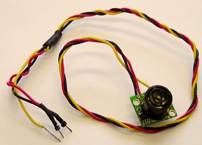
The sensor weâre going to be using in this chapter is the LV-MaxSonar-EZ1 manufactured by MaxBotics (see Figure 4-1), operating at 5 or 3.3 V.
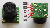
The EZ1 is a versatile ultrasonic range finder and is widely available from various suppliers, including SparkFun, for around $25.
Note
The LV-MaxSonar-EZ1 detects objects from 0 to 6.45 m (approximately 21 ft) with a resolution of 2.5 cm (1 in) for distances beyond 15 cm (6 in). Objects between 0 and 15 cm will range as 15 cm.
Interestingly for our purposes, the sensor provides three different interfaces: analog voltage output, pulse width output, and serial digital output. All three interfaces are active simultaneously. For more information see the product datasheet.
Perhaps the easiest, and most familiar, way to wire the EZ1 sensor is to make use of its analog output. We need only three wires to the sensor, connected to the GND, +5V, and AN pins. See Figure 4-1 and Figure 4-2 for details.
Making use of the EZ1 sensor operating in this mode is fairly trivial. If you connect the 5V and GND pins to their respective counterparts on the Arduino board, and the AN pin to Analog pin A0, the following sketch will send distance measurements to the Arduinoâs serial pins (RX, TX) and to the USB connection:
int ez1Analog = 0; // Analog Pin, A0

void setup() {
   pinMode(ez1Analog,INPUT);
   Serial.begin(9600);
}

void loop() {
   int val = analogRead(ez1Analog);
   if (val > 0) {
      val = val / 2;
      float cm = float(val)*2.54;
      Serial.println( int(cm) ); // cm
   }
}An alternative to using the AN pin on the EZ1 sensor is to use the PW pin and make use of the pulse width output.
Note
The pulse width is 58 ms per cm, or 147 ms per in.
If you disconnect the AN pin, and connect the EZ1âs PW pin to digital pin 5 on the Arduino, which is one of the pins that supports PWM, the following sketch replicates the functionality of the sketch in the preceding section in a slightly different fashion:
int ez1Pulse = 5; // Digital Pin 5 (with PWM)

void setup() {
   pinMode(ez1Pulse,INPUT);
   Serial.begin(9600);
}

void loop() {
   int val = pulseIn(ez1Pulse, HIGH);
   if (val > 0) {
      float cm = val / 58; // pulse width is 58 microsecs per cm
      Serial.println( int(cm) ); // cm
   }
}One of the main reasons I selected the EZ1 as our example sensor for this chapter is that this sensor offers asynchronous serial reporting of measurements in addition to analog and pulse width outputs. This means that we can bypass the Arduino board and the RS-232 to TTL adaptor, and connect the sensor directly to the Redpark cable. Weâll look at how to do that toward the end of the chapter.
Note
The TX output delivers asynchronous serial with an RS-232 format (although voltage range is 0âVcc). Output is an ASCII capital âRâ, followed by three ASCII character digits representing the range in inches (up to a maximum of 255), followed by a carriage return (ASCII character 13).
Although the voltage of 0âVcc is outside the RS-232 standard, most RS-232 devices have sufficient margin to read 0âVcc serial data. The baud rate is 9600, 8 bits, no parity, with one stop bit.
Get iOS Sensor Apps with Arduino now with the O’Reilly learning platform.
O’Reilly members experience books, live events, courses curated by job role, and more from O’Reilly and nearly 200 top publishers.

