CHAPTER 5
Finite Impulse Response Filters
5.1 INTRODUCTION
From the previous two chapters, we have become familiar with the magnitude response of ideal lowpass, highpass, bandpass, and bandstop filters, which was approximated by IIR filters. In the previous chapter, we also discussed the theory and a few prominent procedures for designing the IIR filters.
The general form of the difference equation for a linear, time-invariant, discrete-time system (LTIDT system) is
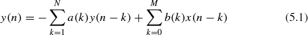
The transfer function for such a system is given by

The transfer function of an FIR filter, in particular, is given by
![]()
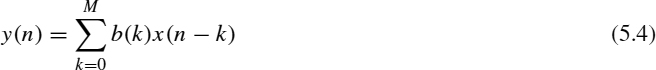
and the difference equation describing this FIR filter is given by
![]()
In this chapter, the properties of the FIR filters and their design will be discussed. When the input function x(n) is the unit sample function δ(n), the output y(n) can be obtained by applying the recursive algorithm on (5.4). We get the output y(n) due to the unit sample input δ(n) to be exactly the values b(0), b(1), b(2), b(3),…, ...
Get Introduction to Digital Signal Processing and Filter Design now with the O’Reilly learning platform.
O’Reilly members experience books, live events, courses curated by job role, and more from O’Reilly and nearly 200 top publishers.

