PROBLEMS
7.1 Determine the logic functions of the multiplexer-based logic circuits in Figure P7.1(a) to (d).
7.2 Determine the logic functions of the multiplexer-based logic circuits in Figure P7.2(a) to (d).
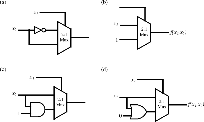
Figure P7.1
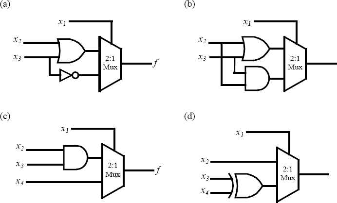
Figure P7.2
7.3 Implement the function of the logic circuit in Figure P7.3 using an 8: 1 multiplexer.
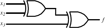
Figure P7.3
7.4 Implement the function of the logic circuit in Figure P7.3 using a 4: 1 multiplexer and additional logic gates.
7.5 Implement the function of the logic circuit in Figure P7.3 using a 2: 1 multiplexer and additional logic gates.
7.6 Implement the function of the logic circuit in Figure P7.6 using a 16: 1 multiplexer.
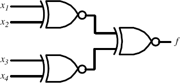
Figure P7.6
7.7 Implement the function of the logic circuit in Figure P7.6 using an 8: 1 multiplexer and additional logic gates.
7.8 Implement the function of the logic circuit in Figure P7.6 using a 4: 1 multiplexer and additional logic gates.
7.9 Implement the function of the logic circuit in Figure P7.6 using a 2: 1 multiplexer and additional logic gates.
7.10 Implement the following logic functions using multiplexers.
7.11 Implement ...
Get Introduction to Digital Systems: Modeling, Synthesis, and Simulation Using VHDL now with the O’Reilly learning platform.
O’Reilly members experience books, live events, courses curated by job role, and more from O’Reilly and nearly 200 top publishers.

