7.5 DEMULTIPLEXERS
The opposite of the multiplexer circuit, logically enough, is the demultiplexer. This circuit takes a single data input and one or more address inputs and selects which of multiple outputs will receive the input signal. The same circuit can also be used as a decoder by using the address inputs as a binary number and producing an output signal on the single output that matches the binary address input. In this application, the data input line functions as a circuit enabler. If the circuit is disabled no output will show activity regardless of the binary input number. A 1 : 2 decoder/demultiplexer circuit uses the same AND gates and the same addressing scheme as the 2 : 1 multiplexer circuit described earlier. The basic difference is that it is the inputs that are combined and the outputs that are separate. By making this change, a 1 : 2 demultiplexer circuit is the inverse of the 2 : 1 multiplexer circuit.
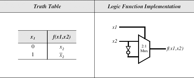
Figure 7.15 XOR Logic Function Implementation with a 2: 1 Multiplexer
Get Introduction to Digital Systems: Modeling, Synthesis, and Simulation Using VHDL now with the O’Reilly learning platform.
O’Reilly members experience books, live events, courses curated by job role, and more from O’Reilly and nearly 200 top publishers.

