5.3 LOGIC SWITCHES
As described earlier, the logic 1 and logic 0 states represent closed and open switches, respectively. We know that the operation of a transistor is similar to that of a simple switch, so logic circuits can be built using transistors. Generally, metal—oxide semiconductor field-effect transistors (MOSFETs) are used to implement the switches. There are two different types of MOSFETs: n-channel and p-channel. An n-channel MOSFET has four electrical terminals, known as gate (G), drain (D), source (S), and body/substrate (B). The operation of an n-channel MOSFET is as follows. When the gate voltage (VG) is greater than the threshold voltage (VTH), a connection is established between the source and the drain and the transistor is said to be turned on and acts as a closed switch. If the gate voltage (VG) is low, there is no connection between the source and the drain and it acts as an open switch. The symbol and the equivalent circuit for a simple n-channel MOSFET are shown in Figure 5.2.
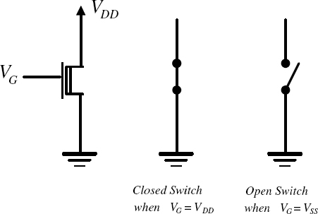
Figure 5.2 NMOS Transistor as a Switch
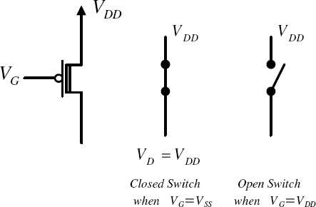
Figure 5.3 PMOS Transistor as a Switch
PMOS transistors behave in exactly the opposite way to NMOS transistors. In this case the transistor acts as an open switch for logic 1 and as a closed switch for logic 0. The PMOS transistor also has four ...
Get Introduction to Digital Systems: Modeling, Synthesis, and Simulation Using VHDL now with the O’Reilly learning platform.
O’Reilly members experience books, live events, courses curated by job role, and more from O’Reilly and nearly 200 top publishers.

