3.12 DESIGN EXAMPLES
3.12.1 Multiplexer
A multiplexer is a combinatorial circuit that has a number (usually, a power of 2) of data inputs (2n) and n select inputs used as a binary number to select one of the data inputs. The multiplexer has a single output, which has the same value as the data input selected. Now let us consider a 2 : 1 multiplexer. As the name indicates, it has two data inputs, x1 and x2, a select input, s, and a single output, y. The output of the circuit will be same as the value of input x1 if s = 0; otherwise the output will be equal to x2. We can construct a truth table based on these requirements. The truth table of a 2: 1 multiplexer is shown in Figure 3.11.
From the truth table we can derive the logical expression for the output y:
![]()
After simplification, the expression is reduced to
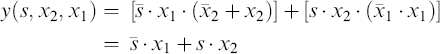
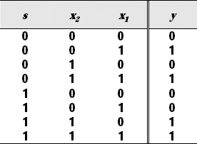
Figure 3.11 Truth Table of a 2:1 Multiplexer
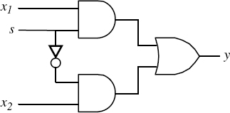
Figure 3.12 Logic Diagram of a 2:1 Multiplexer
which can be realized using one OR gate and two AND gates. The logic diagram for a 2:1 multiplexer is shown in Figure 3.12.
3.12.2 Half-Adder
The half-adder is an example of a simple ...
Get Introduction to Digital Systems: Modeling, Synthesis, and Simulation Using VHDL now with the O’Reilly learning platform.
O’Reilly members experience books, live events, courses curated by job role, and more from O’Reilly and nearly 200 top publishers.

