3.7 TRUTH TABLE
A truth table is generally the first design step. The designer begins with a word statement that describes the function of a digital system. Next, he or she identifies the inputs and outputs of the system and draws a truth table. The inputs and outputs may be single bits or a collection of bits. The truth table consists of input and output columns, which characterize the function of the digital circuit. The input columns consist of all possible combinations of inputs. The maximum number of all possible combinations of inputs is 2n, where n is the number of inputs.
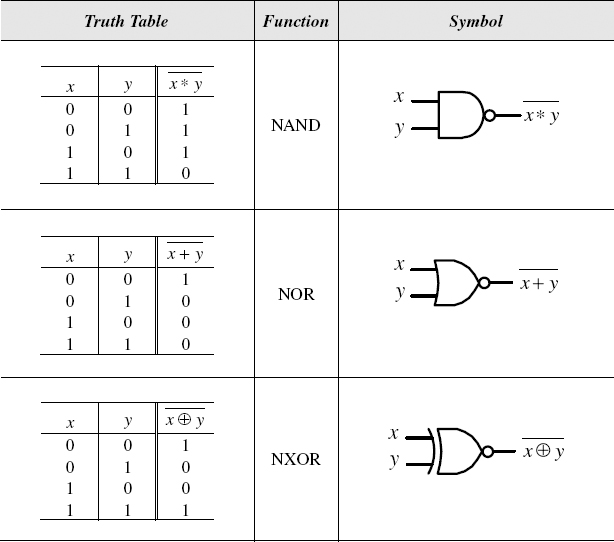
Figure 3.2 NAND, NOR, and NXOR Gates
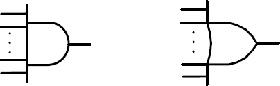
Figure 3.3 Multi-input AND and OR Logic Gates
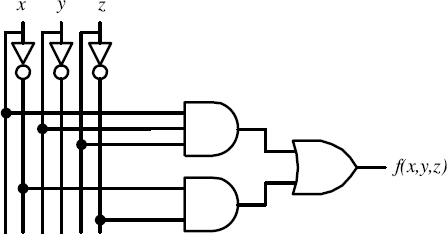
Figure 3.4 Conversion from Logic Function to Circuit Diagram
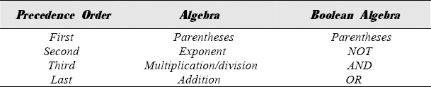
Figure 3.5 Precedence Rules for Elementary Logic Function Conversion
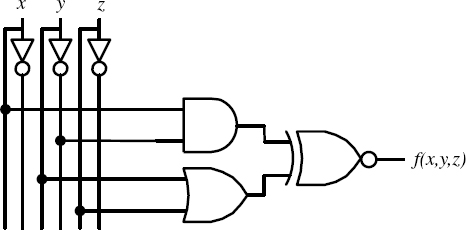
Figure 3.6 Conversion from Circuit Diagram to Logic Expression
Consider the truth table in Figure 3.7. The digital circuit described by this truth table has three inputs (single bit) and one output ...
Get Introduction to Digital Systems: Modeling, Synthesis, and Simulation Using VHDL now with the O’Reilly learning platform.
O’Reilly members experience books, live events, courses curated by job role, and more from O’Reilly and nearly 200 top publishers.

